U.S. Pat. No. 10,092,834
DYNAMIC ALLOCATION OF RENDERING RESOURCES IN A CLOUD GAMING SYSTEM
AssigneeKABUSHIKI KAISHA SQUARE ENIX HOLDINGS
Issue DateMarch 27, 2015
Illustrative Figure
Abstract
Provided is a method that includes generating sets of rendering commands for rendering video content for a client device and directing each of the sets of rendering commands to at least one rendering resource from a group of at least two rendering resources, such that each of the rendering resources has at least some of the sets of rendering commands directed to it. The action of directing may include directing each set of rendering commands to a rendering resource, from among the at least two rendering resources, that is designated as an allocated rendering resource for the client device. The method may further include changing which of the at least two rendering resources is designated as the allocated rendering resource for the client device.
Description
It is to be expressly understood that the description and drawings are only for the purpose of illustration of certain embodiments of the invention and are an aid for understanding. They are not intended to be a definition of the limits of the invention. DETAILED DESCRIPTION I. Cloud Gaming Architecture FIG. 1schematically shows a cloud-based video game system architecture according to a non-limiting embodiment of the present invention. The architecture includes a plurality of client devices120,120A connected to a cloud gaming server system100over the Internet130. Each of the client devices120,120A may connect to the Internet130in any suitable manner, including over a respective local access network (not shown). The cloud gaming server system100may also connect to the Internet130over a local access network (not shown), although the server system100may connect directly to the Internet130without the intermediary of a local access network. Connections between the cloud gaming server system100and one or more of the client devices120,120A may comprise one or more channels. These channels can be made up of physical and/or logical links, and may travel over a variety of physical media, including radio frequency, fiber optic, free-space optical, coaxial and twisted pair. The channels may abide by a protocol such as UDP or TCP/IP. Also, one or more of the channels may be supported a virtual private network (VPN). In some embodiments, one or more of the connections may be session-based. The cloud gaming server system100enables users of the client devices120,120A to play video games, either individually (i.e., a single-player video game) or in groups (i.e., a multiplayer video game). Non-limiting examples of video games may include games that are played for leisure, education and/or sport. A video game may but need not offer participants the possibility of monetary gain. Although only two client devices120,120A are shown, it should be appreciated that ...
It is to be expressly understood that the description and drawings are only for the purpose of illustration of certain embodiments of the invention and are an aid for understanding. They are not intended to be a definition of the limits of the invention.
DETAILED DESCRIPTION
I. Cloud Gaming Architecture
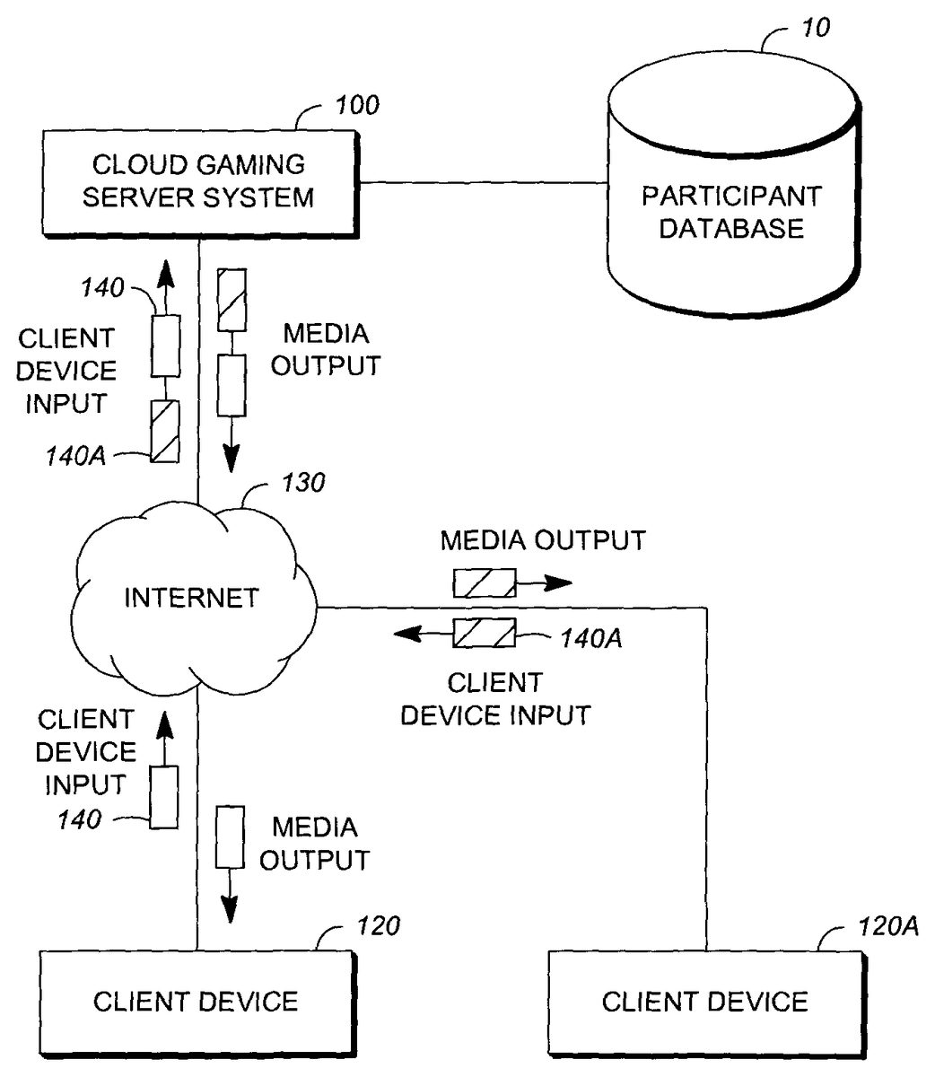
FIG. 1schematically shows a cloud-based video game system architecture according to a non-limiting embodiment of the present invention. The architecture includes a plurality of client devices120,120A connected to a cloud gaming server system100over the Internet130. Each of the client devices120,120A may connect to the Internet130in any suitable manner, including over a respective local access network (not shown). The cloud gaming server system100may also connect to the Internet130over a local access network (not shown), although the server system100may connect directly to the Internet130without the intermediary of a local access network. Connections between the cloud gaming server system100and one or more of the client devices120,120A may comprise one or more channels. These channels can be made up of physical and/or logical links, and may travel over a variety of physical media, including radio frequency, fiber optic, free-space optical, coaxial and twisted pair. The channels may abide by a protocol such as UDP or TCP/IP. Also, one or more of the channels may be supported a virtual private network (VPN). In some embodiments, one or more of the connections may be session-based.
The cloud gaming server system100enables users of the client devices120,120A to play video games, either individually (i.e., a single-player video game) or in groups (i.e., a multiplayer video game). Non-limiting examples of video games may include games that are played for leisure, education and/or sport. A video game may but need not offer participants the possibility of monetary gain. Although only two client devices120,120A are shown, it should be appreciated that the number of client devices in the cloud-based video game system architecture is not particularly limited.
A user of one of the client devices120,120A may register with the cloud gaming server system100as a participant in a video game. The user may register as a “player”, and will have the opportunity to control a character, avatar, race car, cockpit, etc. within a virtual world maintained by the video game. In the case of a multi-player video game, the virtual world is shared by two or more players, and one player's gameplay may affect that of another. In some embodiments, a user of one of the client devices120,120A may register as a non-player “spectator”, whereby such users will observe players' gameplay but otherwise do not control active characters in the game. Unless otherwise indicated, where the term “participant” is used, it is meant to apply equally to players and spectators.
Parameters related to various players and spectators can be stored in a participant database10, which can be part of the cloud gaming server system100or situated remotely therefrom.
The configuration of any given one of the client devices120,120A is not particularly limited. In some embodiments, one or more of the client devices120,120A may be, for example, a personal computer (PC), a home game machine (console such as XBOX™, PS3™, Wii™, etc.), a portable game machine, a smart television, a set-top box (STB), etc. In other embodiments, one or more of the client devices120,120A may be a communication or computing device such as a mobile phone, a personal digital assistant (PDA), or a tablet.
Any given one of the client devices120,120A may be equipped with one or more input devices (such as a touch screen, a keyboard, a game controller, a joystick, etc.) to allow users of the given client device to provide input and participate in a video game. In other embodiments, the user may produce body motion or may wave an external object; these movements are detected by a camera or other sensor (e.g., Kinect™), while software operating within the given client device attempts to correctly guess whether the user intended to provide input to the given client device and, if so, the nature of such input. The given client device translates the received user inputs and detected user movements into “client device input”, which is sent to the cloud gaming server system100over the Internet130. In the illustrated embodiment, client device120produces client device input140, while client device120A produces client device input140A.
The cloud gaming server system100processes the client device input140,140A received from the various client devices120,120A and generates “media output” for the various client devices120,120A. The media output may include frames of encoded video content (i.e., perceived as images when reproduced on a screen) and audio (i.e., perceived as sound when reproduced). The media output is sent over the Internet130in the form of packets. Packets destined for a particular one of the client devices120,120A may be addressed in such a way as to be routed to that device over the Internet130. Each of the client devices120,120A may include circuitry for buffering and processing the media output in the packets received from the cloud gaming server system100, as well as a display for displaying images and a transducer (e.g., a loudspeaker) for outputting audio. Additional output devices may also be provided, such as an electro-mechanical system to induce motion.
It should be appreciated that term “frame” as used herein does not require the existence of a one-to-one correspondence between frames of video content and images as perceived on a screen. That is to say, while it is possible for each frame to contain data representing a respective displayed image in its entirety, it is also possible for a frame to contain data representing only part of an image, and for the image to in fact require two or more frames in order to be properly reconstructed and displayed. By the same token, a frame may contain data representing more than one complete image, such that N images may be represented using M frames, where M<N.
II. Cloud Gaming Server System100(Distributed Architecture)
FIG. 2Ashows one possible non-limiting physical arrangement of components for the cloud gaming server system100. In this embodiment, individual servers within the cloud gaming server system100are configured to carry out specialized functions. For example, a compute server200C may be primarily responsible for tracking state changes in a video game based on user input, while a rendering server200R may be primarily responsible for rendering graphics (video content).
For the purposes of the presently described example embodiment, both client device120and client device120A are assumed to be participating in the video game, either as players or spectators. However, it should be understood that in some cases there may be a single player and no spectator, while in other cases there may be multiple players and a single spectator, in still other cases there may be a single player and multiple spectators and in yet other cases there may be multiple players and multiple spectators.
For the sake of simplicity, the following description refers to a single compute server200C connected to a single rendering server200R. However, it should be appreciated that there may be more than one rendering server200R connected to the same compute server200C, or more than one compute server200C connected to the same rendering server200R. In the case where there are plural rendering servers200R, these may be distributed over any suitable geographic area.
As shown in the non-limiting physical arrangement of components inFIG. 2A, the compute server200C comprises one or more central processing units (CPUs)220C,222C and a random access memory (RAM)230C. The CPUs220C,222C can have access to the RAM230C over a communication bus architecture, for example. While only two CPUs220C,222C are shown, it should be appreciated that a greater number of CPUs, or only a single CPU, may be provided in some example implementations of the compute server200C. The compute server200C also comprises a network interface component (NIC)210C2, where client device input is received over the Internet130from each of the client devices participating in the video game. In the presently described example embodiment, both client device120and client device120A are assumed to be participating in the video game, and therefore the received client device input may include client device input140and client device input140A.
The compute server200C further comprises another network interface component (NIC)210C1, which outputs a plurality of sets of rendering commands204. The sets of rendering commands204output from the compute server200C via the NIC210C1can be sent to the rendering server200R. In one embodiment, the compute server200C can be connected directly to the rendering server200R. In another embodiment, the compute server200C can be connected to the rendering server200R over a network260, which can be the Internet130or another network. A virtual private network (VPN) may be established between the compute server200C and the rendering server200R over the network260.
At the rendering server200R, the sets of rendering commands204sent by the compute server200C are received at a network interface component (NIC)210R1and are directed to one or more CPUs220R,222R. The CPUs220R,222R are connected to a plurality of graphics processing units (GPUs)240R,250R. By way of non-limiting example, GPU240R may include a set of GPU cores242R and a video random access memory (VRAM)246R. Similarly, GPU250R may include a set of GPU cores252R and a video random access memory (VRAM)256R. Each of the CPUs220R,222R may be connected to each of the GPUs240R,250R or to a subset of the GPUs240R,250R. Communication between the CPUs220R,222R and the GPUs240R,250R can be established using, for example, a communications bus architecture. Although only two CPUs and two GPUs are shown, there may be more than two CPUs and GPUs, or even just a single CPU or GPU, in a specific example of implementation of the rendering server200R.
The CPUs220R,222R cooperate with the GPUs240R,250R to convert the sets of rendering commands204into a plurality of graphics output streams for the participating client devices. In the present embodiment, there are two graphics output streams206,206A for the client devices120,120A, respectively. This will be described in further detail later on. The rendering server200R comprises a further network interface component (NIC)210R2, through which the graphics output streams206,206A are sent to the client devices120,120A, respectively.
III. Cloud Gaming Server System100(Hybrid Architecture)
FIG. 2Bshows a second possible non-limiting physical arrangement of components for the cloud gaming server system100. In this embodiment, a hybrid server200H is responsible both for tracking state changes in a video game based on user input, and for rendering graphics (video content).
As shown in the non-limiting physical arrangement of components inFIG. 2B, the hybrid server200H comprises one or more central processing units (CPUs)220H,222H and a random access memory (RAM)230H. The CPUs220H,222H can have access to the RAM230H over a communication bus architecture, for example. While only two CPUs220H,222H are shown, it should be appreciated that a greater number of CPUs, or only a single CPU, may be provided in some example implementations of the hybrid server200H. The hybrid server200H also comprises a network interface component (NIC)210H, where client device input is received over the Internet130from each of the client devices participating in the video game. In the presently described example embodiment, both client device120and client device120A are assumed to be participating in the video game, and therefore the received client device input may include client device input140and client device input140A.
In addition, the CPUs220H,222H are connected to a plurality of graphics processing units (GPUs)240H,250H. By way of non-limiting example, GPU240H may include a set of GPU cores242H and a video random access memory (VRAM)246H. Similarly, GPU250H may include a set of GPU cores252H and a video random access memory (VRAM)256H. Each of the CPUs220H,222H may be connected to each of the GPUs240H,250H or to a subset of the GPUs240H,250H. Communication between the CPUs220H,222H and the GPUs240H,250H can be established using, for example, a communications bus architecture. Although only two CPUs and two GPUs are shown, there may be more than two CPUs and GPUs, or even just a single CPU or GPU, in a specific example of implementation of the hybrid server200H.
The CPUs220H,222H cooperate with the GPUs240H,250H to convert the sets of rendering commands204into graphics output streams for the participating client devices. In this embodiment, there are two graphics output streams206,206A for the participating client devices120,120A, respectively. The graphics output streams206,206A are sent to the client devices120,120A, respectively, via the NIC210H.
IV. Cloud Gaming Server System100(Functionality Overview)
With additional reference now toFIG. 2C, the above-described physical components of the compute server200C and the rendering server200R (inFIG. 2A) and/or of the hybrid server200H (inFIG. 2B) implement a set of functional modules, including a video game functional module270, a rendering functional module280and a video encoder285. According to the non-limiting embodiment ofFIG. 2A, the video game functional module270is implemented by the compute server200C, while the rendering functional module280and the video encoder285are implemented by the rendering server200R. According to the non-limiting embodiment ofFIG. 2B, the hybrid server200H implements the video game functional module270, the rendering functional module280and the video encoder285.
The present example embodiment discusses a single video game functional module270for simplicity of illustration. However, it should be noted that in an actual implementation of the cloud gaming server system100, many video game functional modules similar to the video game functional module270would be executed in parallel. Thus, the cloud gaming server system100could support multiple independent instantiations of the same video game, or multiple different video games, simultaneously. Also, it should be noted that the video games can be single-player video games or multi-player games of any type.
The video game functional module270may be implemented by certain physical components of the compute server200C (inFIG. 2A) or of the hybrid server200H (inFIG. 2B). Specifically, the video game functional module270can be encoded as computer-readable instructions that are executable by a CPU (such as the CPUs220C,222C in the compute server200C or the CPUs220H,222H in the hybrid server200H). The instructions can be tangibly stored in the RAM230C (in the compute server200C) of the RAM230H (in the hybrid server200H) or in another memory area, together with constants, variables and/or other data used by the video game functional module270. In some embodiments, the video game functional module270may be executed within the environment of a virtual machine that may be supported by an operating system that is also being executed by a CPU (such as the CPUs220C,222C in the compute server200C or the CPUs220H,222H in the hybrid server200H).
The rendering functional module280may be implemented by certain physical components of the rendering server200R (inFIG. 2A) or of the hybrid server200H (inFIG. 2B). In an embodiment, the rendering functional module280may take up one or more GPUs (240R,250R inFIG. 2A, 240H, 250HinFIG. 2B) and may or may not utilize CPU resources.
The video encoder285may be implemented by certain physical components of the rendering server200R (inFIG. 2A) or of the hybrid server200H (inFIG. 2B). Those skilled in the art will appreciate that there are various ways in which to implement the video encoder285. In the embodiment ofFIG. 2A, the video encoder285may be implemented by the CPUs220R,222R and/or by the GPUs240R,250R. In the embodiment ofFIG. 2B, the video encoder285may be implemented by the CPUs220H,222H and/or by the GPUs240H,250H. In yet another embodiment, the video encoder285may be implemented by a separate encoder chip (not shown).
In operation, the video game functional module270produces the sets of rendering commands204, based on received client device input. The received client device input may carry data (e.g., an address) identifying the video game functional module for which it is destined, as well as data identifying the user and/or client device from which it originates. Since the users of the client devices120,120A are participants in the video game (i.e., players or spectators), the received client device input includes the client device input140,140A received from the client devices120,120A.
Rendering commands refer to commands which can be used to instruct a specialized graphics processing unit (GPU) to produce a frame of video content or a sequence of frames of video content. Referring toFIG. 2C, the sets of rendering commands204define frames of video content that are ultimately produced by the rendering functional module280. The images represented by these frames change as a function of responses to the client device input140,140A that are programmed into the video game functional module270. For example, the video game functional module270may be programmed in such a way as to respond to certain specific stimuli to provide the user with an experience of progression (with future interaction being made different, more challenging or more exciting), while the response to certain other specific stimuli will provide the user with an experience of regression or termination. Although the instructions for the video game functional module270may be fixed in the form of a binary executable file, the client device input140,140A is unknown until the moment of interaction with a player who uses the corresponding client device120,120A. As a result, there can be a wide variety of possible outcomes, depending on the specific client device input that is provided. This interaction between players/spectators and the video game functional module270via the client devices120,120A can be referred to as “gameplay” or “playing a video game”.
The rendering functional module280processes the plural sets of rendering commands204to create a plurality of video content streams205. Generally, there will be one video content stream205per participant (or, equivalently, per client device). When performing rendering, data for one or more objects represented in three-dimensional space (e.g., physical objects) or two-dimensional space (e.g., text) may be loaded into a cache memory (not shown) of a particular GPU240R,250R,240H,250H. This data may be transformed by the GPU240R,250R,240H,250H into data representative of a two-dimensional image, which may be stored in the appropriate VRAM246R,256R,246H,256H. As such, the VRAM246R,256R,246H,256H may provide temporary storage of picture element (pixel) values for a game screen.
The video encoder285compresses and encodes the video content stream205into streams of compressed video frames. The resultant streams of compressed video frames, referred to as graphics output streams, are produced on a per-client-device basis. In the present example embodiment, the video encoder285produces graphics output stream206for client device120and graphics output stream206A for client device120A. Additional functional modules may be provided for formatting the video frames into packets so that they can be transmitted over the Internet130.
V. Generation of Rendering Commands
Generation of rendering commands by the video game functional module270is now described in greater detail with reference toFIGS. 2C, 3A and 3B. Specifically, execution of the video game functional module270involves several processes, including a main game process300A and one or more graphics control processes300B, which are described herein below in greater detail.
Main Game Process
A first process, referred to as the main game process, is described with reference toFIG. 3A. The main game process300A executes continually. As part of the main game process300A, there is provided an action310A, during which client device input may be received. If the video game is a single-player video game without the possibility of spectating, then client device input (e.g., client device input140) from a single client device (e.g., client device120) is received as part of action310A. If the video game is a multi-player video game or is a single-player video game with the possibility of spectating, then the client device input (e.g., the client device input140and140A) from one or more client devices (e.g., the client devices120and120A) may be received as part of action310A.
By way of non-limiting example, the input from a given client device may convey that the user of the given client device wishes to cause a character under his or her control to move, jump, kick, turn, swing, pull, grab, etc. Alternatively or in addition, the input from the given client device may convey a menu selection made by the user of the given client device in order to change one or more audio, video or gameplay settings, to load/save a game or to create or join a network session. Alternatively or in addition, the input from the given client device may convey that the user of the given client device wishes to select a particular camera view (e.g., first-person or third-person) or reposition his or her viewpoint within the virtual world.
At action320A, the game state may be updated based at least in part on the client device input received at action310A and other parameters. Updating the game state may involve the following actions:
Firstly, updating the game state may involve updating certain properties of the participants (player or spectator) associated with the client devices from which the client device input may have been received. These properties may be stored in the participant database10. Examples of participant properties that may be maintained in the participant database10and updated at action320A can include a camera view selection (e.g., 1stperson, 3rdperson), a mode of play, a selected audio or video setting, a skill level, a customer grade (e.g., guest, premium, etc.).
Secondly, updating the game state may involve updating the attributes of certain objects in the virtual world based on an interpretation of the client device input. The objects whose attributes are to be updated may in some cases be represented by two- or three-dimensional models and may include playing characters, non-playing characters and other objects. In the case of a playing character, attributes that can be updated may include the object's position, strength, weapons/armor, lifetime left, special powers, speed/direction (velocity), animation, visual effects, energy, ammunition, etc. In the case of other objects (such as background, vegetation, buildings, vehicles, score board, etc.), attributes that can be updated may include the object's position, velocity, animation, damage/health, visual effects, textual content, etc.
It should be appreciated that parameters other than client device input can influence the above properties (of participants) and attributes (of virtual world objects). For example, various timers (such as elapsed time, time since a particular event, virtual time of day, total number of players, a participant's geographic location, etc.) can have an effect on various aspects of the game state.
Once the game state has been updated further to execution of action320A, the main game process300A returns to action310A, whereupon new client device input received since the last pass through the main game process is gathered and processed.
Graphics Control Process
A second process, referred to as the graphics control process, is now described with reference toFIG. 3B. The graphics control process300B may execute continually, and there may be a plurality separate graphics control processes300B, each of which results in a respective one of the sets of rendering commands204. In the case of a single-player video game without the possibility of spectating, there is only one player and therefore only one resulting set of rendering commands204, and thus the graphics control process300B may execute as an extension of the main game process300A described above. In the case of a multi-player video game, multiple distinct sets of rendering commands need to be generated for the multiple players, and therefore multiple graphics control processes300B may execute in parallel. In the case of a single-player game with the possibility of spectating, there may again be only a single set of rendering commands204, and therefore a single graphics control process3006may execute in the video game functional module270, but the resulting video content stream may be duplicated for the spectators by the rendering functional module280. Of course, these are only examples of implementation and are not to be taken as limiting.
At action310B of the graphics control process300B for a given participant requiring a distinct video content stream, the video game functional module270determines the objects to be rendered for the given participant. This action can include identifying the following types of objects:
Firstly, this action can include identifying those objects from the virtual world that are in the “game screen rendering range” (also known as a “scene”) for the given participant. The game screen rendering range includes the portion of the virtual world that would be “visible” from the perspective of the given participant's camera. This depends on the position and orientation of that camera relative to the objects in the virtual world. In a non-limiting example of implementation of action310B, a frustum can be applied to the virtual world, and the objects within that frustum are retained or marked. The frustum has an apex which is situated at the location of the given participant's camera and has a directionality also defined by the directionality of that camera.
Secondly, this action can include identifying additional objects that do not appear in the virtual world, but which nevertheless are to be rendered for the given participant. For example, these additional objects may include textual messages, graphical warnings and dashboard indicators, to name a few non-limiting possibilities.
At action320B, the video game functional module270generates a set of commands for transforming rendering into graphics (video content) the objects that were identified at action310B. Rendering may refer to the transformation of 3-D or 2-D coordinates of an object or group of objects into data representative of a displayable image, in accordance with the viewing perspective and prevailing lighting conditions. This can be achieved using any number of different algorithms and techniques, for example as described in “Computer Graphics and Geometric Modelling: Implementation & Algorithms”, Max K. Agoston, Springer-Verlag London Limited, 2005, hereby incorporated by reference herein.
At action330B, the rendering commands generated at action320B are output to the rendering functional module280. This may involve packetizing the generated rendering commands into a set of rendering commands204that is sent to the rendering functional module280.
Those skilled in the art will appreciate that multiple instantiations of the graphics control process300B described above may be executed, resulting in multiple sets of rendering commands204.
VI. Generation of Graphics Output
The rendering functional module280interprets the plural sets of rendering commands204and produces a plural set of video content streams205, one for each participating client device. Rendering may be achieved by the GPUs240R,250R,240H,250H under control of the CPUs220R,222R (inFIG. 2A) or220H,222H (inFIG. 2B). The rate at which frames of video content are produced for a participating client device may be referred to as the frame rate.
In an embodiment where there are N participants, there may be N sets of rendering commands204(one for each participant) and also N video content streams205(one for each participant). In that case, rendering functionality is not shared among the participants. However, the N video content streams205may also be created from M sets of rendering commands204(where M<N), such that fewer sets of rendering commands need to be processed by the rendering functional module280. In that case, the rendering functional unit280may perform sharing or duplication in order to generate a larger number of video content streams205from a smaller number of sets of rendering commands204. Such sharing or duplication may be prevalent when multiple participants (e.g., spectators) desire to view the same camera perspective. Thus, the rendering functional module280may perform functions such as duplicating a created video content stream for one or more spectators.
Next, the video content in each of the video content streams205are encoded by the video encoder285, resulting in a sequence of encoded video content associated with each client device, referred to as a graphics output stream. In the example embodiments ofFIGS. 2A-2C, the sequence of encoded video content destined for client device120is referred to as graphics output stream206, while the sequence of encoded video content destined for client device120A is referred to as graphics output stream206A.
The video encoder285can be a device (or set of computer-readable instructions) that enables or carries out or defines a video compression or decompression algorithm for digital video. Video compression transforms an original stream of digital image data (expressed in terms of pixel locations, color values, etc.) into an output stream of digital image data that conveys substantially the same information but using fewer bits. Any suitable compression algorithm may be used. In addition to data compression, the encoding process used to encode a particular frame of video content may or may not apply cryptographic encryption.
The graphics output streams206,206A created in the above manner are sent over the Internet130to the respective client devices. By way of non-limiting example, the graphics output streams may be segmented and formatted into packets, each having a header and a payload. The header of a packet containing video content for a given participant may include a network address of the client device associated with the given participant, while the payload may include the video content, in whole or in part. In a non-limiting embodiment, the identity and/or version of the compression algorithm used to encode certain video content may be encoded in the content of one or more packets that convey that video content. Other methods of transmitting the encoded video content will occur to those of skill in the art.
While the present description focuses on the rendering of video content representative of individual 2-D images, the present invention does not exclude the possibility of rendering video content representative of multiple 2-D images per frame to create a 3-D effect.
VII. Game Screen Reproduction at Client Device
Reference is now made toFIG. 4A, which shows operation of the client device associated with a given participant, which may be client device120or client device120A, by way of non-limiting example.
At action410A, encoded frames of video content (in one of the graphics output streams206,206A) is received over the Internet130from the rendering server200R (FIG. 2A) or from the hybrid server200H (FIG. 2B), depending on the embodiment.
At action420A, the encoded frames of video content are decoded in accordance with the decompression algorithm that is complementary to the compression algorithm used in the encoding process. In a non-limiting embodiment, the identity or version of the compression algorithm used to encode the video content may be known in advance. In other embodiments, the identity or version of the compression algorithm used to encode the video content may accompany the video content itself.
At action430A, the (decoded) frames of video content are processed. This can include placing the decoded frames of video content in a buffer, performing error correction, reordering and/or combining the data in multiple successive frames, alpha blending, interpolating portions of missing data, and so on. The result can be video content representative of a final image to be presented to the user on a per-frame basis.
At action440A, the final image is output via the output mechanism of the client device. For example, a composite video frame can be displayed on the display of the client device.
VIII. Audio Generation
A third process, referred to as the audio generation process, is now described with reference toFIG. 3C. The audio generation process executes continually for each participant requiring a distinct audio stream. In one embodiment, the audio generation process may execute independently of the graphics control process300B. In another embodiment, execution of the audio generation process and the graphics control process may be coordinated.
At action310C, the video game functional module270determines the sounds to be produced. Specifically, this action can include identifying those sounds associated with objects in the virtual world that dominate the acoustic landscape, due to their volume (loudness) and/or proximity to the participant within the virtual world.
At action320C, the video game functional module270generates an audio segment. The duration of the audio segment may span the duration of a video frame, although in some embodiments, audio segments may be generated less frequently than video frames, while in other embodiments, audio segments may be generated more frequently than video frames.
At action330C, the audio segment is encoded, e.g., by an audio encoder, resulting in an encoded audio segment. The audio encoder can be a device (or set of instructions) that enables or carries out or defines an audio compression or decompression algorithm. Audio compression transforms an original stream of digital audio (expressed as a sound wave changing in amplitude and phase over time) into an output stream of digital audio data that conveys substantially the same information but using fewer bits. Any suitable compression algorithm may be used. In addition to audio compression, the encoding process used to encode a particular audio segment may or may not apply cryptographic encryption.
It should be appreciated that in some embodiments, the audio segments may be generated by specialized hardware (e.g., a sound card) in either the compute server200C (FIG. 2A) or the hybrid server200H (FIG. 2B). In an alternative embodiment that may be applicable to the distributed arrangement ofFIG. 2A, the audio segment may be parametrized into speech parameters (e.g., LPC parameters) by the video game functional module270, and the speech parameters can be redistributed to the destination client device (e.g., client device120or client device120A) by the rendering server200R.
The encoded audio created in the above manner is sent over the Internet130. By way of non-limiting example, the encoded audio input may be broken down and formatted into packets, each having a header and a payload. The header may carry an address of a client device associated with the participant for whom the audio generation process is being executed, while the payload may include the encoded audio. In a non-limiting embodiment, the identity and/or version of the compression algorithm used to encode a given audio segment may be encoded in the content of one or more packets that convey the given segment. Other methods of transmitting the encoded audio will occur to those of skill in the art.
Reference is now made toFIG. 4B, which shows operation of the client device associated with a given participant, which may be client device120or client device120A, by way of non-limiting example.
At action410B, an encoded audio segment is received from the compute server200C, the rendering server200R or the hybrid server200H (depending on the embodiment). At action420B, the encoded audio is decoded in accordance with the decompression algorithm that is complementary to the compression algorithm used in the encoding process. In a non-limiting embodiment, the identity or version of the compression algorithm used to encode the audio segment may be specified in the content of one or more packets that convey the audio segment.
At action430B, the (decoded) audio segments are processed. This can include placing the decoded audio segments in a buffer, performing error correction, combining multiple successive waveforms, and so on. The result can be a final sound to be presented to the user on a per-frame basis.
At action440B, the final generated sound is output via the output mechanism of the client device. For example, the sound is played through a sound card or loudspeaker of the client device.
IX. Specific Description of Non-Limiting Embodiments
A more detailed description of certain non-limiting embodiments of the present invention is now provided.
Reference is made toFIG. 5A, in which there is shown a control server510, a plurality of rendering resources501and a client device520. The rendering resources501receive sets of rendering commands from the control server510and produce video content that is encoded and sent to the client device520over a network such as the Internet130. Accordingly, one or more of the rendering resources501may generally resemble the rendering server200R inFIG. 2A, and the client device520could be any of the aforementioned client devices120,120A. The rendering resources501may be geographically dispersed, such as amongst a plurality of buildings or cities, for example. Alternatively, two or more of the rendering resources501may be situated in the same physical location, such as in the same building or city.
In a non-limiting embodiment, the design of the control server510can be based upon the compute server210C inFIG. 2A. Therefore, the control server510can be a game control server and its software configuration can include the aforementioned video game functional module270, which generates sets of rendering commands (or “rendering command sets”). A rendering command set can be interpreted by a rendering resource (e.g., a server reachable over the Internet), resulting in the creation of one or more frames of video content. For the purposes of the present illustrated example, the rendering command sets generated by the video game functional module270are denoted5301,5302, etc. Also, in the present illustrated example, each of the rendering command sets5301,5302, etc. corresponds to one frame of video content (respectively denoted5401,5402, etc.) that is ultimately created by the rendering resources501. However, this one-to-one correspondence is not to be understood as a limitation of the present invention since, generally speaking, a rendering command set may correspond to one or more ultimately created frames of video content.
The control server510includes suitable hardware, software and/or control logic for implementing an output controller512, which intercepts the rendering command sets5301,5302, etc. produced by the video game functional module270and determines where to send each rendering command set. Stated differently, at a particular moment in time, each of the rendering command sets5301,5302, etc. is sent to one of the rendering resources501that has been designated as an “allocated” rendering resource at that moment in time. An identifier of the “allocated rendering resource”, which varies over time, can be provided to the output controller512by a rendering resource allocation module514. Thus, the functionality of the output controller512, for a given client device (such as the client device520), may be similar to that of a demultiplexer having one input and a plurality of outputs, and being controlled by the rendering resource allocation module514.
The rendering resource allocation module514may be implemented using the hardware/software/control logic resources of the control server510. From a functional point of view, the rendering resource allocation module514monitors one or more parameters and makes a rendering resource reallocation decision based upon the monitored parameter(s). The decision to change which rendering resource is designated as the allocated rendering resource can be made on a per-participant (or per-client-device) basis, that is to say, there may be a list of participant/client devices stored in memory, each participant/client device associated with a particular rendering resource that is designated as the allocated rendering resource for that participant/client device at that moment in time. The identity of the allocated rendering resource for a given client such as the client device520may change dynamically (i.e., over time) in order to accommodate a variety of operational conditions and constraints.
Once a decision to change which rendering resource is designated as the allocated rendering resource for the client device520has been made by the rendering resource allocation module514, this decision may be communicated directly to the output controller512in the form of a control signal516. The control signal516may specifically identify the newly allocated rendering resource. The identifier of the allocated rendering resource can be encoded as that respective server's IP address, for example. Alternatively, the decision could be communicated in an indirect fashion. For example, the identifier of the currently allocated rendering resource (e.g., a server's IP address or other identifier) may be stored at the control server510in a memory location (not shown) that is at least readable by the output controller512and at least writable by the rendering resource allocation module514. The output controller512may be configured to poll this memory location on a regular basis. In such a scenario, the rendering resource allocation module514may simply write the identifier of the newly allocated rendering resource to the aforementioned memory location, and this fresh information will be available to the output controller512when it reads from the memory location. Other mechanisms for conveying the rendering resource reallocation decision to the output controller512are of course possible.
In operation, the video game functional module270generates a sequence of rendering command sets which, for the purposes of the present example illustrated inFIG. 5B, is assumed to include rendering command sets5301,5302,5303,5304,5305and5306, in that order. While only six rendering command sets are shown, this is not to be understood as a limitation of the present invention. Also, let it be assumed that there are two rendering resources501A and501B in the cloud gaming system although it should be understood that there is no particular limit on the number of rendering resources501that could be employed in a practical realization of the present invention.
Now, let it further be assumed that the allocated rendering resource for the client device520at the time of sending out rendering command set5301is rendering resource501A. The identity of the allocated rendering resource is known to the output controller512, which directs rendering command set5301to rendering resource501A. Let it also be assumed that this situation persists for some time, allowing rendering command sets5302and5303to be similarly sent to rendering resource501A. Rendering resource501A transforms the rendering command sets5301,5302and5303into respective frames of video content5401,5402and5403. Frames5401,5402and5403are sent to the client device520after being encoded and/or compressed by rendering resource501A. Although in this example, each rendering command set corresponds to a single respective frame of video content, this one-to-one correspondence is not a limitation, as it is possible for a given rendering command set to result in the creation of multiple frames of video content.
Assume now that the rendering resource allocation module514decides to change which rendering resource is the allocated rendering resource for the client device520, so that it designates rendering resource501B as the allocated rendering resource for client device520. This decision to change the identity of the allocated rendering resource for the client device520may be the result of a rendering resource allocation algorithm implemented by a logic circuit or stored program. From this point on, the output controller512begins sending rendering command sets to the newly allocated rendering resource, namely rendering resource501B. Accordingly, rendering command sets5304,5305and5306are sent to rendering resource501B, which transforms the rendering command sets5304,5305and5306into respective frames of video content5404,5405and5406. frames of video content5404,5405and5406may be encoded and/or compressed, this time by rendering resource501B, before being sent to the client device520.
For its part, the client device520receives frames of video content from each of the two rendering resources510A,501B, but at different times corresponding generally to the times during which the given rendering resource (either501A or510B) was the allocated rendering resource for the client device520. Specifically, the client device520receives frames of video content5401,5402and5403from rendering resource501A (which were sent during the time period when rendering resource501A was the allocated rendering resource for the client device520). Also, the client device520receives frames of video content5404,5405and5406from rendering resource501B (which were sent during the time period when rendering resource501B was the allocated rendering resource for the client device520).
Upon receipt at the client device520, the received frames of video content may be placed into a buffer522and decoded. Since there is no guarantee that, for example, frame5403will be received before frame5404, it may be desirable to implement a reordering functional unit524, which is responsible for ensuring that the images subsequently displayed by the client device520are displayed in the correct order. As such, the buffer522and the reordering functional unit524can implement action430A ofFIG. 4Athat was described previously. Once the received frames of video content5401,5402,5403,5404,5405and5406have been reordered (if necessary) at the client device520, they may be placed into a frame buffer526. The frame buffer526can be the source of the images that are to be displayed on the display of the client device520in the context of action440A ofFIG. 4A.
The order of the rendering command sets5301,5302,5303,5304,5305and5306(and therefore the order of the corresponding frames of video content5401,5402,5403,5404,5405and5406) may be encoded in the form of a sequence identifier that is embedded in or otherwise sent by the output controller512with each of the rendering command sets5301,5302,5303,5304,5305and5306and is propagated to the client device520by the rendering resources510A,501B. By way of illustration, inFIG. 5B, sequence identifiers ID_1, ID_2, ID_3, ID_4, ID_5and ID_6are sent by the output controller512with rendering command sets5301,5302,5303,5304,5305and5306, respectively. These sequence identifiers are re-transmitted with frames of video content5401,5402,5403,5404,5405and5406, respectively, regardless of which rendering resource is responsible for generating a particular frame. Of course, the skilled person will realize that there are other techniques to achieve proper ordering.
It will be observed from the above description that the responsibility for generating frames of video content is transferred among the rendering resources501in a dynamic fashion.
In some embodiments, it may be useful to alert the client device520as to the identifier of any newly allocated rendering resource from which it can expect to receive frames of video content, as well as the sequence identifier of the first frame that is expected to be received from the newly allocated rendering resource. To accomplish this in the aforementioned example of operation, it is possible for the output controller512to precede the transmission of first rendering command set that is under the responsibility of the newly allocated rendering resource by a message that is sent to the client device520.
FIG. 6Ashows the situation in which the output controller512inserts an alert610into a rendering command set sent to rendering resource501A (in this case, rendering command set5303). The alert610includes the identifier of rendering resource501B and sequence identifier ID_4. Generally speaking, the alert could include the sequence identifiers of one or more rendering command sets scheduled to be sent to the newly allocated rendering resource. Rendering resource501A propagates the alert610to the client device520, which will consequently know that subsequent frames, beginning with the frame having sequence identifier ID_4(namely, frame5404), will be received from rendering resource501B.
FIG. 6Bshows the situation in which the same information as in the aforementioned alert610is sent as an out-of-band message620over a control link630established over the Internet130between the rendering resource allocation module514and the client device520.
FIG. 6Cshows another way of carrying out the transition, namely by having the output controller512duplicately transmit rendering command sets to both rendering resources501A,501B, starting with one or more rendering command sets prior to changing the identity of the allocated rendering resource. In this case, rendering command set5301is shown as being sent only to rendering resource501A, while the next two rendering command sets5302and5303are shown as being sent to both the formerly allocated rendering resource (rendering resource501A) and the newly allocated rendering resource (rendering resource501B). Thereafter, rendering command sets5304,5305and5306are, as before, only sent to rendering resource501B. The rendering resources501A,501B respond by generating corresponding frames of video content, resulting in some duplicate frames (namely, frames6002and6003carrying sequence identifiers ID_2and ID_3) being sent to the client device520. At the client device520, the reordering functional unit524can be equipped with functionality to remove duplicate video content from the input buffer522.
Conversely, it is also within the scope of the present invention to carry out the transition by having the output controller512duplicately transmit rendering command sets to both rendering resources510A,501B, starting with one or more rendering command sets after (rather than prior to) changing the identity of the allocated rendering resource. This is shown inFIG. 6D, where rendering command sets5301,5302and5303are shown as being sent only to rendering resource501A, while rendering command sets5304and5305are shown as being sent to both the formerly allocated rendering resource (rendering resource501A) and the newly allocated rendering resource (rendering resource501B). Finally, rendering command set5306is only sent to rendering resource501B. The rendering resources501A,501B respond by generating corresponding frames of video content, resulting in some duplicate frames (namely, frames6004and6005carrying sequence identifiers ID_4and ID_5) being sent to the client device520. At the client device520, the reordering functional unit524can be equipped with functionality to remove duplicate frames from the input buffer522.
In another embodiment, each of the rendering resources501A,501B may add its own signature when transmitting a particular frame to the client device520in order to allow the client device520to recognize which rendering resource has sent the particular frame when it is received.
Still other techniques for transitioning from a formerly allocated rendering resource to a newly allocated rendering resource will be understood by those of skill in the art to be within the scope of the present invention.
Rendering Resource Allocation Algorithm
The rendering resource allocation module514implements a rendering resource allocation algorithm in order to make a rendering resource reallocation decision, which is a decision as to the appropriate moment for changing the identity of the allocated rendering resource from the currently allocated rendering resource to a newly allocated rendering resource. This decision, which is carried out on a per-client-device basis, could be based on variety of conditions.
A first example of a condition used for making a rendering resource reallocation decision may be related to the transmission distance between the client device520and the currently allocated rendering resource. Specifically, consider that the transmission distance between the client device520and the currently allocated rendering resource (e.g., rendering resource501A) is being monitored, along with the transmission distance between the client device520and one or more other rendering resources (e.g., rendering resource501B). In this example, the condition leading to reallocation may be deemed to be satisfied when the transmission distance between the client device520and the currently allocated rendering resource (e.g., rendering resource501A) exceeds the transmission distance between the client device and another rendering resource (e.g., rendering resource501B). This other rendering resource (e.g., rendering resource501B) then becomes the newly allocated rendering resource for the client device520.
According to the first example mentioned above, consider a player who is in a vehicle (such as a car, train or plane) and using a mobile device's wireless connection (e.g., over cellular/WiMax/WiFi). Consider also that the player is moving away from the currently allocated rendering resource (e.g., rendering resource501A) and finds himself/herself approaching a neighboring server (e.g., rendering resource501B) that could be used for creating and streaming frames of video content. As some point, the communication latency between the mobile device and the neighboring server (e.g., rendering resource501B) could be better (i.e., smaller) than the one being experienced using the currently allocated rendering resource (e.g., rendering resource501A). This could warrant changing to the neighboring server (e.g., rendering resource501B) as the newly allocated rendering resource.
It is noted that the change in the identity of the allocated rendering resource for the client device520may occur independently of the client device's wireless connection. That is to say, the same wireless connection may be preserved, but the source of the frames of video content over that connection changes dynamically. Conversely, the wireless connection may change for a variety of reasons, but this does not imply that the identity of the allocated rendering resource has to change. That is to say, the decision to transition between rendering resources may be independent of the decision to hand off the wireless connection.
Similarly, the change in which rendering resource is the allocated rendering resource for the client device520may occur independently of the client device's Internet connection. That is to say, the same Internet connection may be continuously maintained while the source of the frames of video content over that Internet connection changes from rendering resource501A to rendering resource501B. Alternatively, different Internet connections can be established over which frames of video content are received from different sources.
A second example of a condition used for making a rendering resource reallocation decision may be related to the measured communication latency between the client device520and the currently allocated rendering resource. Specifically, consider that the communication latency between the client device520and the currently allocated rendering resource (e.g., rendering resource501A) is being monitored, along with the communication latency between the client device520and one or more other rendering resources (e.g., rendering resource501B). In this example, the condition leading to reallocation may be deemed to be satisfied when the communication latency between the client device520and the currently allocated rendering resource (e.g., rendering resource501A) starts to exceed the communication latency between the client device520and another rendering resource (e.g., rendering resource501B). This other rendering resource (e.g., rendering resource501B) then becomes the newly allocated rendering resource for the client device520.
According to the second example mentioned above, even though a player's client device may not be physically moving with any significant velocity, there may be factors that impact the communication latency, such as network congestion. Meanwhile, the client device may have access to a second rendering resource (e.g., rendering resource501B) for which the communication latency is less than with respect to the currently allocated rendering resource (e.g., rendering resource501A). As such, this could warrant designating the second rendering resource (e.g., rendering resource501B) as the allocated rendering resource for the client device.
A third example of a condition used for making a rendering resource reallocation decision could may be related to the computational load of the currently allocated rendering resource. Specifically, consider that the computational load of the currently allocated rendering resource (e.g., rendering resource501A) is being monitored, along with the computational load of one or more other rendering resources (e.g., rendering resource501B). In this example, the condition leading to reallocation may be deemed to be satisfied when the computational load of the currently allocated rendering resource (e.g., rendering resource501A) starts to exceed the computational load of one of these other rendering resources (e.g., rendering resource501B) for a certain period of time. This other rendering resource (e.g., rendering resource501B) then becomes the newly allocated rendering resource.
A fourth example of a condition used for making a rendering resource reallocation decision may be related to the quality of the communications link between the client device520and the currently allocated rendering resource.
Specifically, consider that the quality of the communications link between the client device520and the currently allocated rendering resource (e.g., rendering resource501A) is being monitored, along with the quality of the communications link between the client device520and one or more other rendering resources (e.g., rendering resource501B). Non-limiting indicators of quality could be signal strength, error rate, retransmission rate, etc. In this example, the condition leading to reallocation may be deemed to be satisfied when the quality of the communications link between the client device520and the currently allocated rendering resource (e.g., rendering resource501A) drops below the quality of the communications link between the client device520and another rendering resource (e.g., rendering resource501B). This other rendering resource (e.g., rendering resource501B) could then be designated as the allocated rendering resource.
A fifth example of a condition used for making a rendering resource reallocation decision may be related to the geographic zone where the client device520is located. Specifically, consider that the location or jurisdiction where the client device520is located is being monitored, and consider that there is a correspondence between rendering resources and assigned geographic zones. This correspondence may be maintained in a database that is accessible to the output controller512, and may be stored locally to the control server510or available over the Internet130. In this example, the condition leading to reallocation may be deemed to be satisfied when the client device520migrates into the geographic zone assigned to a different rendering resource than the one to which it is currently allocated. This other rendering resource then becomes the newly allocated rendering resource for the client device.
Those skilled in the art should appreciate that merely because a new rendering resource has been identified, or merely because the condition for re-allocation has been satisfied, this does not imply that re-allocation must take place immediately. Specifically, additional conditions (or pre-requisites) may need to be satisfied before reallocation may take place.
In a first example, the output controller512ensures that the level of action in the game is sufficiently low before making a change to the identity of the allocated rendering resource. Accordingly, a level of action in the game is determined and compared to a predetermined threshold. In one embodiment, shown inFIG. 8, an action determiner800is situated at the client device820and a message805conveying a level of action is fed back to the output controller812at the control server810. The action determiner800processes frames of video content in order to output the level of action805. The level of action805can be measured based on detected visual or acoustical characteristics, including the relative number/magnitude of pixel variations from one frame to the next, the audio volume (including nuances such as crescendo), etc. Pattern detection can also be used to detect motion (and speed) of graphical elements throughout a video sequence. Also, a variety of processing algorithms could be used in order to carry out shot boundary detection. In other embodiments, the level of action can be determined by analysis of the rendering commands and therefore measurements can be done by the control server510or by the rendering resources501A,501B. In still other embodiments, the level of action can be determined based on the rate of input received from the client device520. For example, a high degree of input received from the client device520may be used as a proxy for inferring a correspondingly high level of action in the video game.
In a second example, the output controller512ensures that the game is at a natural break point before making a change to the identity of the allocated rendering resource. Accordingly, progress throughout the game is monitored in terms of whether the player has just completed a level, has just started a level, is partly through a level, is in the process of a major battle, etc. Information about where in the game the player is located could be provided by the video game functional module270.
In a third example, the rendering resource allocation module514waits until the player has paused the game before authorizing a change in the identity of the allocated rendering resource. This can enhance the seamlessness of the change in which rendering resource is designated as the allocated rendering resource. For example, consider that the player pauses the game either explicitly (which causes the issuance of a command to the video game functional module270), or implicitly (e.g., by shutting off his/her mobile device before a flight). This paused state is detected by the video game functional module270, which informs the output controller512. At this point, the output controller512can proceed with changing the identity of the allocated rendering resource. However, there may be no effect of this change until the player turns on the mobile device upon arrival at his/her destination.
It should also be appreciated that after the identity of the allocated rendering resource has changed, it may need to be changed again at a future time. Accordingly, a subsequent rendering resource reallocation decision may be made, based on the various conditions specified above, to change the identity of the allocated rendering resource from the recently allocated rendering resource to a further newly allocated rendering resource. This further newly allocated rendering resource may be the same rendering resource as the one that was the allocated rendering resource before the most recent change, or it may be a different rendering resource altogether.
Thus, it will be appreciated that there has been described a method by virtue of which the control server generates sets of rendering commands for rendering video content for a client device and directs each of the sets of rendering commands to at least one rendering resource from a group of at least two rendering resources such that each of the rendering resources has at least some of the sets of rendering commands directed to it.
Variant (Collaborative/Distributed decision Making)
It will be appreciated that the parameters used in the rendering resource allocation decision (such as the transmission distance, communication latency, computational load and/or communications link quality, to name a few non-limiting possibilities) could be measured by the rendering resources501A,501B and communicated back to the control server510for processing and interpretation by the rendering resource allocation module514. Alternatively, the parameters could be estimated or inferred by the control server510based on various sources of information such as network reports. In yet another embodiment, certain parameters could even be measured by the client device520and reported back to the rendering resource allocation module514for decision making.
In yet another embodiment, depicted inFIG. 7, the rendering resource allocation algorithm could be wholly or partly incorporated into a rendering resource allocation module714at the client device, denoted720. Thus, based on the parameters (e.g., signal strength, communication latency, etc.) available for two or more rendering resources at the client device720, the rendering resource allocation module714makes a decision as to when is the appropriate time to change the identity of the allocated rendering resource, and this information could be relayed back to the output control module512of the control server710in the form of a trigger750. The trigger750could provide the identifier of the rendering resource that is to be designated as the newly allocated rendering resource for the client device720. In such an implementation, there is no need for a rendering resource allocation module at the control server710, as the rendering resource allocation module714is being implemented in the client device720. A hybrid implementation whereby the rendering resource allocation algorithm is distributed between the control server and the client device (and possibly the rendering resources501A,501B) is also within the scope of the present invention.
Variant (redundancy)
In a variant, each of the rendering command sets is sent to each of at least two rendering resources among the rendering resources501. At the client device520, duplicate video content will be received from multiple rendering resources. The received frames can be buffered (and reordered in those cases where they are out of order). Of course, since there will be multiple copies of certain video content, these could be either not stored, or discarded before re-ordering.
With this type of approach, the design of the output controller514at the control server510is simplified, since it only needs to duplicate the rendering command sets, without burdening itself with designating an allocated rendering resource for the client device520. The trade-off is that more bandwidth is consumed over the Internet130, since there is a duplication of the rendering command sets (and resulting frames). In fact, the greater the number of rendering resources handling duplicate rendering command sets, the greater the bandwidth requirement. Also in this variant, the client device520should be designed to incorporate a feature for removing duplicate video frames that will be received from multiple rendering resources.
Persons skilled in the art should appreciate that the above-discussed embodiments are to be considered illustrative and not restrictive. Also it should be appreciated that additional elements that may be needed for operation of certain embodiments of the present invention may not have been described or illustrated, as they are assumed to be within the purview of the person of ordinary skill in the art. Moreover, certain embodiments of the present invention may be free of, may lack and/or may function without any element that is not specifically disclosed herein.
Finally, certain embodiments of the present invention may present aspects recited by the following enumerated clauses which are not claims:
1. A computer implemented method, comprising:generating sets of rendering commands for rendering video content for a client device;directing each of the sets of rendering commands to at least one rendering resource from a group of at least two rendering resources such that each of the rendering resources has at least some of the sets of rendering commands directed to it.
2. The computer implemented method defined in clause 1, wherein the directing comprises directing each set of rendering commands to a rendering resource, from among the at least two rendering resources, that is designated as an allocated rendering resource for the client device.
3. The computer implemented method defined in clause 2, further comprising:changing which of the at least two rendering resources is designated as the allocated rendering resource for the client device.
4. The computer implemented method defined in clause 3, further comprising:determining a transmission distance between the allocated rendering resource and the client device;wherein the changing is carried out based on the determined transmission distance.
5. The computer implemented method defined in clause 4, wherein the changing is carried out in case the determined transmission distance exceeds a predetermined threshold.
6. The computer implemented method defined in clause 3, further comprising:during the time when a first one of the at least two rendering resources is designated as the allocated rendering resource for the client device, identifying a second one of the at least two rendering resources that is at a shorter transmission distance to the device than the first rendering resource;wherein the changing comprises designating the second rendering resource as the allocated rendering resource for the client device.
7. The computer implemented method defined in clause 3, further comprising:determining a communication latency between the allocated rendering resource and the client device;wherein the changing is carried out based on the determined communication latency.
8. The computer implemented method defined in clause 7, wherein the changing is carried out in case the determined communication latency exceeds a predetermined threshold.
9. The computer implemented method defined in clause 3, further comprising:during the time when a first one of the at least two rendering resources is designated as the allocated rendering resource for the client device, identifying a second one of the rendering resources having a lower communication latency to the device than the first rendering resource;wherein the changing comprises designating the second rendering resource as the allocated rendering resource for the client device.
10. The computer implemented method defined in clause 3, further comprising:determining a computational load of the allocated rendering resource;wherein the changing is carried out based on the determined computational load.
11. The computer implemented method defined in clause 10, wherein the changing is carried out in case the determined computational load exceeds a predetermined threshold.
12. The computer implemented method defined in clause 9, further comprising:during the time when a first one of the at least two rendering resources is designated as the allocated rendering resource for the client device, identifying a second one of the rendering resources having a lower computational load than the first rendering resource;wherein the changing comprises designating the second rendering resource as the allocated rendering resource for the client device.
13. The computer implemented method defined in clause 3, further comprising:determining a quality of a communications link between the allocated rendering resource and the client device;wherein the changing is carried out based on the determined quality of the communications link.
14. The computer implemented method defined in clause 13, wherein the changing is carried out in case the determined quality falls below a predetermined threshold.
15. The computer implemented method defined in clause 14, further comprising:during the time when a first one of the at least two rendering resources is designated as the allocated rendering resource for the client device, identifying a second one of the rendering resources that terminates a communications link having a greater quality than the communications link between the device and the first rendering resource;wherein the changing comprises designating the second rendering resource as the allocated rendering resource for the client device.
16. The computer implemented method defined in clause 3, further comprising:determining a geographic location of the client device;consulting a database specifying an association between geographic zones and respective rendering resources;wherein the changing is carried out based on the determined geographic location and the contents of the database.
17. The computer implemented method defined in clause 16, wherein the changing is carried out in case the device is determined to have migrated into a geographic zone associated with a different rendering resource than the one that is designated as the allocated rendering resource for the client device.
18. The computer implemented method defined in clause 3, wherein the changing is carried out in response to determining that a condition has been met.
19. The computer implemented method defined in clause 18, wherein prior to determining that the condition has been met, a first rendering resource from among the at least two rendering resources is designated as the allocated rendering resource for the client device, and wherein the changing comprises designating a second rendering resource from among the at least two rendering resources as the allocated rendering resource for the client device.
20. The computer implemented method defined in clause 19, further comprising:in response to determining that the condition has been met, duplicately sending one or more sets of rendering commands to both the first and second rendering resources, and then sending subsequent sets of rendering commands only to the second rendering resource.
21. The computer implemented method defined in clause 19, further comprising:in response to determining that the condition has been met, sending a message to the client device, the message identifying the second rendering resource.
22. The computer implemented method defined in clause 21, further comprising:transmitting a respective sequence identifier with each set of rendering commands, the sequence identifier indicating a position of the respective set of rendering commands relative to other sets of rendering commands;wherein the message conveys the sequence identifier of one or more sets of rendering commands scheduled to be directed to the second rendering resource.
23. The computer implemented method defined in clause 22, wherein the message is sent together with at least one rendering command set directed to the first rendering resource.
24. The computer implemented method defined in clause 22, wherein the message is sent to the device in an out-of-band message.
25. The computer implemented method defined in clause 19, further comprising:determining a transmission distance between the client device and each of the first and second rendering resources;wherein the condition is considered to have been met in case the device is determined to be at a shorter transmission distance to the second rendering resource than to the first rendering resource.
26. The computer implemented method defined in clause 19, further comprising:determining a communication latency between the client device and each of the first and second rendering resources;wherein the condition is considered to have been met in case the communication latency involving the second rendering resource is lower than the communication latency involving the first rendering resource.
27. The computer implemented method defined in clause 19, further comprising:determining a computational load of each of the first and second rendering resources;wherein the condition is considered to have been met in case the computation load of the second rendering resource is lower than the computational load of the first rendering resource.
28. The computer implemented method defined in clause 19, further comprising:determining a quality of a communications link between the client device and each of the first and second rendering resources;wherein the condition is considered to have been met in case the quality of the link involving the second rendering resource is greater than the quality of the link involving the first rendering resource.
29. The method defined in clause 1, wherein the changing is carried out in response to detecting receipt of a trigger.
30. The method defined in clause 29, further comprising:receiving the trigger from the client device.
31. The method defined in clause 30, wherein the trigger conveys an instruction to change which of the at least two rendering resources is designated as the allocated rendering resource.
32. The method defined in clause 30, wherein the trigger conveys an identifier of a second rendering resource to be designated as the allocated rendering resource.
33. The method defined in clause 3, further comprising:maintaining in a memory an identifier of the rendering resource that is designated as the allocated rendering resource.
34. The computer implemented method defined in clause 3, wherein each set of rendering commands defines an image having a position in time relative to other images defined by other sets of rendering commands.
35. The method defined in clause 34, further comprising:processing the sets of rendering commands by the allocated rendering resource to produce corresponding video content for the client device.
36. The method defined in clause 35, further comprising:causing the video content to be transmitted over the Internet to the client device.
37. The computer implemented method defined in clause 36, wherein the video content comprises data representative of video game images.
38. The method defined in clause 1, implemented by a control server, wherein the at least two rendering resources comprise rendering servers that are remote from the control server.
39. The method defined in clause 38, further comprising receiving control input from the client device over the Internet.
40. The computer implemented method defined in clause 39, further comprising executing a video game program for the client device.
41. The method defined in clause 40, further comprising updating a game state of the video game based on the control input from the client device.
42. The method defined in clause 41, wherein updating the game state includes updating objects in a 3D virtual environment.
43. The method defined in clause 42, wherein the sets of rendering commands are generated based on a projection of the 3D virtual environment from a perspective associated with the client device.
44. The computer implemented method defined in clause 3, further comprising:determining a level of action in the video game;wherein the changing is carried out in case the level of action in the video game is determined to be low.
45. The computer implemented method defined in clause 3, further comprising:determining progress in the video game;wherein the changing is carried out in case the progress in the video game is determined to be at a break in the game.
46. The computer implemented method defined in clause 3, further comprising:determining whether the video game has been paused;wherein the changing is carried out in case the video game is determined to have been paused.
47. The computer implemented method defined in clause 19, wherein changing which of the at least two rendering resources is designated as the allocated rendering resource further comprises second changing which of the at least two rendering resources is designated as the allocated rendering resource for the client device in response to determining that a second condition has been met.
48. The computer implemented method defined in clause 47, the second changing comprises designating a new rendering resource from among the at least two rendering resources as the allocated rendering resource for the client device.
49. The computer implemented method defined in clause 48, wherein the new rendering resource is a third rendering resource that is neither the first rendering resource nor the second rendering resource.
50. The computer implemented method defined in clause 48, wherein the new rendering resource is the first rendering resource.
51. The computer implemented method defined in clause 1, wherein the directing comprises directing at least some of the sets of rendering commands to each of the at least two rendering resources.
52. The computer implemented method defined in clause 1, wherein the directing comprises directing each of the sets of rendering commands to no more than one of the at least two rendering resources.
53. The computer implemented method defined in clause 1, wherein the directing comprises directing first ones of the sets of rendering commands to a first one of the rendering resources prior to determining that a condition has been met and directing second ones of the sets of rendering commands to a second one of the rendering resources after determining that the condition has been met.
54. A computer-readable storage medium comprising computer-readable instructions which, when executed by a computing entity, cause the computing entity to implement a method that comprises:generating sets of rendering commands for rendering video content for a client device;directing each of the sets of rendering commands to at least one rendering resource from a group of at least two rendering resources such that each of the rendering resources has at least some of the sets of rendering commands directed to it.
55. The computer-readable storage medium defined in clause 54, wherein the directing comprises directing each set of rendering commands to a rendering resource, from among the at least two rendering resources, that is designated as an allocated rendering resource for the participant.
56. The computer-readable storage medium defined in clause 55, wherein the method further comprises:changing which of the at least two rendering resources is designated as the allocated rendering resource for the participant.
57. The computer-readable storage medium defined in clause 55, wherein the changing is carried out in response to determining that a condition has been met.
58. The computer-readable storage medium defined in clause 57, wherein prior to determining that the condition has been met, a first rendering resource from among the at least two rendering resources is designated as the allocated rendering resource for the client device, and wherein the changing comprises designating a second rendering resource from among the at least two rendering resources as the allocated rendering resource for the client device.
59. The computer-readable storage medium defined in clause 54, wherein the directing comprises directing at least some of the sets of rendering commands to each of the at least two rendering resources.
60. The computer-readable storage medium defined in clause 54, wherein the directing comprises directing each of the sets of rendering commands to no more than one of the at least two rendering resources.
61. The computer-readable storage medium defined in clause 54, wherein the directing comprises directing first ones of the sets of rendering commands to a first one of the rendering resources prior to determining that a condition has been met and directing second ones of the sets of rendering commands to a second one of the rendering resources after determining that the condition has been met.
62. An apparatus, comprising:a control module for generating sets of rendering commands for rendering video content for a client device;an output controller for directing each of the sets of rendering commands to at least one rendering resource from a group at least two rendering resources such that each of the rendering resources has at least some of the sets of rendering commands directed to it.
63. The apparatus defined in clause 62, wherein the directing comprises directing each set of rendering commands to a rendering resource, from among the at least two rendering resources, that is designated as an allocated rendering resource for the participant, and wherein the server further comprises:rendering resource allocation logic for making a decision about which of the rendering resources is the designated rendering resource and for informing the output controller of the decision.
64. A server system, comprising:a first rendering server configured for generating first video frames for a client device based on first sets of rendering commands received while the first rendering server is designated as an allocated rendering server for the client device, and for sending the first video frames to the client device; anda second rendering server configured for generating second video frames for the client device based on second sets of rendering commands received while the second rendering server is designated as an allocated rendering server for the client device, and for sending the second video frames to the client device.
65. The server system defined in clause 64, wherein the first and second rendering servers are configured for receiving a sequence identifier with each of the first and second sets of rendering commands, respectively, and for propagating each received sequence identifier with a corresponding one or more of the first and second video frames, respectively, sent to the client device.
66. The server system defined in clause 64, further comprising:a control server configured for sending the first sets of rendering commands to the first rendering server prior to determining that a condition has been met and for sending the second sets of rendering commands to the second rendering server after determining that the condition has been met.
67. A method for execution by a processing entity of a client device engaged in a session over the Internet with a control server, comprising:sending input to the control server over the Internet;responsive to the input, receiving first video content via the Internet from a first rendering resource and receiving second video content via the Internet from a second rendering resource different from the first rendering resource;displaying the first video content and then the second video content via a display of the client device.
68. The method defined in clause 67, wherein at least some of the second video content is received after at least some of the first video content.
69. The method defined in clause 67, wherein the first video content is generated by the first rendering resource.
70. The method defined in clause 69, wherein the second video content is generated by the second rendering resource.
71. The method defined in clause 70, wherein the first and second video content is generated based on sets of rendering commands received from a single source.
72. The method defined in clause 67, further comprising:while receiving the first video content, determining that the client device is at a shorter distance from the second rendering resource than from the first rendering resource;transmitting a trigger to the control server;wherein receiving the second video content begins after transmitting the trigger.
73. The method defined in clause 67, further comprising:while receiving the first video content, determining that a communication latency between the client device and the second rendering resource is lower than the communication latency between the client device and the first rendering resource;transmitting a trigger to the control server;wherein receiving the second video content begins after transmitting the trigger.
74. The method defined in clause 67, further comprising:while receiving the first video content, determining that a signal strength from the second rendering resource is greater than the signal strength from the first rendering resource;transmitting a trigger to the control server;wherein receiving the second video content begins after transmitting the trigger.
75. The method defined in clause 67, further comprising:receiving external input from a user of the client device;transforming the external input the input sent to the control server.
76. The method defined in clause 67, wherein the first and second video content is received over the same, continuously maintained Internet connection.
77. The method defined in clause 67, wherein the first video content is received over a first Internet connection and wherein the second video content is received over a second Internet connection distinct from the first Internet connection.
78. The method defined in clause 67, wherein the first and second video content is received in an encoded form, the method further comprising:decoding the video content to obtain decoded video content;wherein the displayed video content is the decoded video content.
79. The method defined in clause 67, wherein the first and second video content is divided into frames, the method further comprising:receiving a sequence identifier with each of the received frames;reordering the received frames in accordance with the sequence identifiers.
Those skilled in the art will also appreciate that additional adaptations and modifications of the described embodiments can be made. The scope of the invention, therefore, is not to be limited by the above description of specific embodiments but rather is defined by the claims attached hereto.
Claims
- A computer implemented method, comprising: generating sets of rendering commands for rendering video content for a client device, the video content comprising game images, the rendering commands being generated based on client device input received during gameplay;directing each of the sets of rendering commands to at least one rendering resource from a group of at least two rendering resources such that each of the at least two rendering resources has at least some of the sets of rendering commands directed thereto, one of the at least two rendering resources being designated as an allocated rendering resource for the client device;processing the sets of rendering commands directed to the allocated rendering resource for the client device to produce corresponding video content comprising a portion of the game images for the client device;based on determining that at least one condition has been met, changing which of the at least two rendering resources is designated as the allocated rendering resource for the client device;and sending a message to the client device to alert the client device as to an identity of a rendering resource newly designated as the allocated rendering resource for the client device.
- The computer implemented method defined in claim 1 , further comprising: determining a transmission distance between the allocated rendering resource and the client device, wherein the determining that the at least one condition has been met comprises determining that the transmission distance between the allocated rendering resource and the client device is greater than a transmission distance between another one of the at least two rendering resources and the client device.
- The computer implemented method defined in claim 1 , further comprising: determining a communication latency between the allocated rendering resource and the client device, wherein the determining that the at least one condition has been met comprises determining that the communication latency between the allocated rendering resource and the client device is greater than a communication latency between another one of the at least two rendering resources and the client device.
- The computer implemented method defined in claim 1 , further comprising: determining a computational load of the allocated rendering resource, wherein the determining that the at least one condition has been met comprises determining that the computational load of the allocated rendering resource is greater than a computational load of another one of the at least two rendering resources.
- The computer implemented method defined in claim 1 , further comprising: determining a quality of a communications link between the allocated rendering resource and the client device, wherein the determining that the at least one condition has been met comprises determining that the quality of the communications link between the allocated rendering resource and the client device is below a quality of a communications link between another one of the at least two rendering resources and the client device.
- The computer implemented method defined in claim 1 , further comprising: determining a geographic location of the client device;and consulting a database specifying associations between geographic zones and the at least two rendering resources, wherein the determining that the at least one condition has been met comprises determining, based on the determined geographic location and contents of the database, that the client device has migrated into one of the geographic zones assigned to one of the at least two rendering resources other than the allocated rendering resource.
- The computer implemented method defined in claim 1 , wherein, prior to determining that the at least one condition has been met, a first rendering resource from among the at least two rendering resources is designated as the allocated rendering resource for the client device, and wherein the changing comprises designating a second rendering resource from among the at least two rendering resources as the allocated rendering resource for the client device.
- The computer implemented method defined in claim 7 , further comprising: in response to the determining that the at least one condition has been met, duplicately sending one or more sets of rendering commands to both the first rendering resource and the second rendering resource, and then sending subsequent sets of rendering commands only to the second rendering resource.
- The method defined in claim 1 , further comprising receiving a trigger from the client device, wherein the changing is carried out in response to detecting receipt of the trigger.
- The computer implemented method defined in claim 1 , further comprising: determining progress in a video game, wherein the changing is carried out only in a case the progress in the video game is determined to be at a break in the video game.
- The computer implemented method defined in claim 1 , further comprising: determining whether a video game has been paused, wherein the changing is carried out only in a case the video game is determined to have been paused.
- A non-transitory computer-readable storage medium comprising computer-readable instructions which, when executed by a computing entity, cause the computing entity to implement a method that comprises: generating sets of rendering commands for rendering video content for a client device, the video content comprising game images, the rendering commands being generated based on client device input received during gameplay;directing each of the sets of rendering commands to at least one rendering resource from a group of at least two rendering resources such that each of the at least two rendering resources has at least some of the sets of rendering commands directed thereto, one of the at least two rendering resources being designated as an allocated rendering resource for the client device;processing the sets of rendering commands directed to the allocated rendering resource for the client device to produce corresponding video content comprising a portion of the game images for the client device;based on determining that at least one condition has been met, changing which of the at least two rendering resources is designated as the allocated rendering resource for the client device;and sending a message to the client device to alert the client device as to an identity of a rendering resource newly designated as the allocated rendering resource for the client device.
- A server system, comprising: a first rendering server configured for generating first video frames for a client device based on first sets of rendering commands received while the first rendering server is designated as an allocated rendering server for the client device, and for sending the first video frames to the client device;and a second rendering server configured for generating second video frames for the client device based on second sets of rendering commands received while the second rendering server is designated as an allocated rendering server for the client device, and for sending the second video frames to the client device;wherein the first rendering server is configured to be changed to the second rendering server upon at least one condition having been met.
- A method for execution by a processing entity of a client device engaged in a session over the Internet with a control server, the method comprising: sending input, received during gameplay, to the control server over the Internet;and responsive to the input;receiving first video content via the Internet from a first rendering resource;receiving a message that alerts the client device of an identity of a second rendering resource different from the first rendering resource;and receiving second video content via the Internet from the second rendering resource;and displaying the first video content and then the second video content via a display of the client device.
- The method of claim 14 , wherein the message is responsive to at least one condition having been met.
- The server of system of claim 13 , wherein at least one of the first rendering server and the second rendering server is configured to transmit a message that alerts the client device of an identity of the second rendering server.
- The non-transitory computer-readable storage medium of claim 12 , wherein the instructions, when executed by the computing entity, cause the computing entity to further perform determining progress in a video game, and wherein the changing is carried out only in a case the progress in the video game is determined to be at a break in the video game.
- The non-transitory computer-readable storage medium of claim 12 , wherein the instructions, when executed by the computing entity, cause the computing entity to further perform determining a transmission distance between the allocated rendering resource and the client device, and wherein the determining that the at least one condition has been met comprises determining that the transmission distance between the allocated rendering resource and the client device is greater than a transmission distance between another one of the at least two rendering resources and the client device.
- The non-transitory computer-readable storage medium of claim 12 , wherein the instructions, when executed by the computing entity, cause the computing entity to further perform determining a communication latency between the allocated rendering resource and the client device, and wherein the determining that the at least one condition has been met comprises determining that the communication latency between the allocated rendering resource and the client device is greater than a communication latency between another one of the at least two rendering resources and the client device.
- The non-transitory computer-readable storage medium of claim 12 , wherein the instructions, when executed by the computing entity, cause the computing entity to further perform determining a computational load of the allocated rendering resource, and wherein the determining that the at least one condition has been met comprises determining that the computational load of the allocated rendering resource is greater than a computational load of another one of the at least two rendering resources.
Disclaimer: Data collected from the USPTO and may be malformed, incomplete, and/or otherwise inaccurate.