U.S. Pat. No. 10,092,832
GAME SYSTEM, GAME DEVICE, AND GAME CONTROLLER FOR STORING OPERATION TIMING FOR LATER TRANSMISSION
AssigneeNINTENDO CO., LTD.
Issue DateApril 19, 2017
Illustrative Figure
Abstract
An example game controller has a memory storing first and second operation times at which the operations onto the first and second operation members have been performed, and a first control circuit. The first control circuit transmits to a main body apparatus, a connection signal. The main body apparatus has a second control circuit. The second control circuit performs processing for establishing connection with the game controller in response to the connection signal, and transmits to the game controller, a request signal when the processing for establishing connection is completed. The first control circuit transmits the information on the operation time stored in the memory to the main body apparatus in response to the request signal. The second control circuit determines whether or not the operations satisfy a predetermined condition based on the operation time, and registers a first operation scheme when a result of determination is affirmative.
Description
DETAILED DESCRIPTION OF NON-LIMITING EXAMPLE EMBODIMENTS This embodiment will be described in detail with reference to the drawings. The same or corresponding elements in the drawings have the same reference characters allotted and description thereof will not be repeated. [A. Information Processing System] An apparatus configuration relating to an information processing system based on the present embodiment will be described. The information processing system according to the present embodiment is configured at least with an information processing apparatus described below. For example, an information processing apparatus may be a portable (also referred to as mobile) device such as a portable game device, a portable telephone, or a smartphone, a stationary apparatus such as a personal computer or a home game console, or a large apparatus such as an arcade game machine. In the present example, a game device representing one example of an information processing apparatus will be described by way of example. Though a game controller provided for a game device will be described in the present example by way of example of an operation apparatus, limitation in particular to a game controller is not intended and any operation apparatus may be applicable so long as it functions as an input device capable of transmitting operation data to an information processing apparatus. (a1: Overall Configuration of Game Device) FIG. 1is an example non-limiting schematic diagram showing appearance of a game device1according to the present embodiment. As shown inFIG. 1, game device1includes a main body apparatus2, a left controller3, and a right controller4. Main body apparatus2includes a display12representing one example of a display portion and performs various types of processing including game processing in game device1. FIG. 2is an example non-limiting schematic diagram showing appearance of another manner of game device1according to the present embodiment. As shown inFIG. 2, left ...
DETAILED DESCRIPTION OF NON-LIMITING EXAMPLE EMBODIMENTS
This embodiment will be described in detail with reference to the drawings. The same or corresponding elements in the drawings have the same reference characters allotted and description thereof will not be repeated.
[A. Information Processing System]
An apparatus configuration relating to an information processing system based on the present embodiment will be described. The information processing system according to the present embodiment is configured at least with an information processing apparatus described below.
For example, an information processing apparatus may be a portable (also referred to as mobile) device such as a portable game device, a portable telephone, or a smartphone, a stationary apparatus such as a personal computer or a home game console, or a large apparatus such as an arcade game machine. In the present example, a game device representing one example of an information processing apparatus will be described by way of example. Though a game controller provided for a game device will be described in the present example by way of example of an operation apparatus, limitation in particular to a game controller is not intended and any operation apparatus may be applicable so long as it functions as an input device capable of transmitting operation data to an information processing apparatus.
(a1: Overall Configuration of Game Device)
FIG. 1is an example non-limiting schematic diagram showing appearance of a game device1according to the present embodiment.
As shown inFIG. 1, game device1includes a main body apparatus2, a left controller3, and a right controller4. Main body apparatus2includes a display12representing one example of a display portion and performs various types of processing including game processing in game device1.
FIG. 2is an example non-limiting schematic diagram showing appearance of another manner of game device1according to the present embodiment.
As shown inFIG. 2, left controller3and right controller4may be constructed as being detachable from main body apparatus2. Left controller3and right controller4may integrally be constructed or left controller3and right controller4may be constructed as separate apparatuses. Thus, left controller3and right controller4corresponding to an operation portion may be constructed separately from main body apparatus2.
Left controller3can be attached to a left side (a side of a positive direction of an x axis shown inFIG. 1) of main body apparatus2. Right controller4can be attached to a right side (a side of a negative direction of the x axis shown inFIG. 1) of main body apparatus2. In the description below, left controller3and right controller4may collectively be referred to as a “controller”. A more specific configuration example of main body apparatus2, left controller3, and right controller4will be described below.
(a2: Structure of Main Body Apparatus)
FIG. 3is an example non-limiting diagram of main body apparatus2according to the present embodiment when viewed from six sides.
Referring toFIG. 3, main body apparatus2has a housing11substantially in a form of a plate.
A main surface of housing11(that is, a front surface or a surface where display12is provided) is substantially in a rectangular shape.
A shape and a size of housing11can arbitrarily be designed.
(1) Member Provided on Main Surface of Housing11
As shown inFIGS. 1 to 3, display12is provided on the main surface of housing11of main body apparatus2. Display12shows an image obtained or generated by main body apparatus2(which may be a still image or moving images). When game processing is performed, display12shows a virtual space and an object in the virtual space. Though display12is typically implemented by a liquid crystal display (LCD), a display apparatus of any type can be adopted.
A touch panel13is provided on a screen of display12. Typically, a device of a type accepting a multi-touch input (for example, a capacitance type) is adopted as touch panel13. For example, a device of any type such as a device of a type accepting a single-touch input (for example, a resistive film type) can be adopted as touch panel13.
Speaker holes11aand11bare provided in the main surface of housing11of main body apparatus2and sound generated from a speaker (a speaker88shown inFIG. 7) arranged in housing11is output through speaker holes11aand11b.
Two speakers are provided in main body apparatus2and speaker holes11aand11bare provided in correspondence with respective positions of a left speaker and a right speaker. Speaker hole11ais provided on a left side of display12in correspondence with the left speaker and speaker hole11bis provided on a right side of display12in correspondence with the right speaker.
(2) Member Provided on Left Side Surface of Housing11
A left rail member15for removably attaching left controller3to main body apparatus2is provided in a left side surface of housing11. Left rail member15extends along an up-down direction in the left side surface of housing11. Left rail member15is in a shape allowing engagement thereof with a slider (a slider40shown inFIG. 4) for left controller3. A slide mechanism is formed by left rail member15and slider40. With such a slide mechanism, left controller3can slidably and removably be attached to main body apparatus2.
A left terminal17is provided in the left side surface of housing11. Left terminal17is a terminal for wired communication between main body apparatus2and left controller3. Left terminal17is provided at a position where it comes in contact with a terminal (a terminal42shown inFIG. 4) of left controller3when left controller3is attached to main body apparatus2. Left terminal17should be arranged at any position where the left terminal of main body apparatus2and the terminal of left controller3are in contact with each other while left controller3is attached to main body apparatus2. By way of example, as shown inFIG. 3, left terminal17is provided around a lower end portion of left rail member15.
(3) Member Provided in Right Side Surface of Housing11
As shown inFIG. 3, a feature similar to the feature provided in the left side surface is provided in a right side surface of housing11. A right rail member19for removably attaching right controller4to main body apparatus2is provided in the right side surface of housing11. Right rail member19extends along the up-down direction in the right side surface of housing11. Right rail member19is in a shape allowing engagement thereof with a slider (a slider62shown inFIG. 5) for right controller4. A slide mechanism is formed by right rail member19and slider62. With such a slide mechanism, right controller4can slidably and removably be attached to main body apparatus2.
Right rail member19is in a shape similar to left rail member15. Right rail member19is in a grooved shape similar in cross-sectional shape to left rail member15. Right rail member19does not have to be exactly the same in shape as left rail member15. For example, another embodiment may be constructed such that slider62for right controller4cannot be engaged with left rail member15and/or slider40for left controller3cannot be engaged with right rail member19by making a size and/or a shape of the groove different between left rail member15and right rail member19.
A right terminal21is provided in the right side surface of housing11. Right terminal21is a terminal for wired communication between main body apparatus2and right controller4. Right terminal21is provided at a position where it comes in contact with a terminal (a terminal64shown inFIG. 5) of right controller4when right controller4is attached to main body apparatus2. Right terminal21should be arranged at any position where the right terminal of main body apparatus2and the terminal of right controller4are in contact with each other while right controller4is attached to main body apparatus2. By way of example, as shown inFIG. 3, right terminal21is provided around a lower end portion of right rail member19.
(4) Member Provided on Upper Side Surface of Housing11
As shown inFIG. 3, a first slot23for attaching a storage medium of a first type is provided in an upper side surface of housing11. A lid portion which can be opened and closed is provided in an opening in first slot23as a typical feature, and a storage medium of the first type can be inserted in first slot23while the lid portion is open. The storage medium of the first type is, for example, a storage medium exclusively designed for game device1and a game device of the same type (for example, a dedicated memory card). The storage medium of the first type is used, for example, for storing data used in main body apparatus2(for example, data saved for an application) and/or a program executed in main body apparatus2(for example, a program for an application).
A power button28for switching on and off main body apparatus2is provided on the upper side surface of housing11.
An audio input and output terminal25(specifically an earphone jack) is provided in the upper side surface of housing11. A microphone or an earphone can be attached to audio input and output terminal25.
(5) Member Provided on Lower Side Surface of Housing11
As shown inFIG. 3, a lower terminal27for wired communication between main body apparatus2and a cradle5which will be described later is provided in a lower side surface of housing11. Lower terminal27is provided at a position where it comes in contact with a terminal of cradle5when main body apparatus2is attached to cradle5. Typically, a universal serial bus (USB) connector (more specifically, a female connector) can be adopted as lower terminal27.
A position, a shape, and the number of components (specifically, a button, a slot, and a terminal) provided in housing11described above can arbitrarily be designed. For example, in another embodiment, power button28or first slot23may be provided in another side surface or a rear surface of housing11. Some of the components do not have to be provided.
(a3: Structure of Left Controller)
FIG. 4is an example non-limiting diagram of left controller3according to the present embodiment when viewed from six sides.
Referring toFIG. 4, left controller3has a housing31substantially in a form of a plate. A main surface of housing31(that is, a front surface or a surface on a side of a negative direction of a z axis shown inFIG. 1) is substantially in a rectangular shape. Housing31is in a vertically long shape, that is, long in the up-down direction (that is, a direction of a y axis shown inFIG. 1).
Left controller3can be used with its main surface being vertically oriented or with its surface being horizontally oriented when a user holds the left controller while the left controller is detached from main body apparatus2.
A shape and a size of housing31can arbitrarily be designed. In another embodiment, housing31may be constructed into a shape other than a shape substantially in a form of a plate. Housing31does not have to be rectangular, and for example, a semicircular shape may be adopted. Housing31does not have to vertically be long.
A length of housing31in the up-down direction is preferably substantially the same as a length in the up-down direction of housing11of main body apparatus2. A thickness of housing31(that is, a length in a front-rear direction or a length in the direction of the z axis shown inFIG. 1) is preferably substantially the same as a thickness of housing11of main body apparatus2. Therefore, when left controller3is attached to main body apparatus2(seeFIG. 1), a user can hold main body apparatus2and left controller3as if they were an integrated apparatus.
A left corner portion of the main surface of housing31is rounded more than a right corner portion. A portion of connection between an upper side surface and a left side surface of housing31and a portion of connection between a lower side surface and the left side surface of housing31are rounded more than a portion of connection between the upper side surface and a right side surface and a portion of connection between the lower side surface and the right side surface (that is, a curve of beveling is great). Therefore, when left controller3is attached to main body apparatus2(see FIG.1), the left side of game device1is rounded and hence such a shape facilitates holding by a user.
An analog stick32is provided in left controller3. As shown inFIG. 4, analog stick32is provided on the main surface of housing31. Analog stick32represents one example of a direction instruction portion with which a direction can be input. Analog stick32includes a stick member which can be tilted in all directions (that is, a 360° direction including up, down, left, right, and diagonal directions) in parallel to the main surface of housing31. The analog stick is an analog input device with which a user can input a direction in accordance with a direction of tilt by titling the stick member. Analog stick32may further be constructed to be able to give an input of magnitude in accordance with an angle of tilt in addition to input of a direction in accordance with a direction of tilt when the stick member is tilted. Alternatively, a slide stick may implement the direction instruction portion. The slide stick is an input portion having a stick member slidable in all directions in parallel to the main surface of housing31, and the user can give an input in accordance with a direction of slide by sliding the stick member. The slide stick may further be constructed also to give an input of magnitude in accordance with an amount of slide. Alternatively, the direction instruction portion may be implemented as an input portion indicating a direction through an operation to press a button. For example, the direction instruction portion may be implemented as an input portion indicating a direction with a cross-shaped key or four buttons corresponding to up, down, left, and right directions, respectively. In the present embodiment, an input can be given by pressing the stick member (in the direction perpendicular to housing31). Analog stick32in the present embodiment is an input portion with which an input of a direction and magnitude in accordance with a direction of tilt and an amount of tilt of the stick member can be given and an input resulting from pressing of the stick member can be given.
Left controller3includes four operation buttons33to36(specifically, a right direction button33, a down direction button34, an up direction button35, and a left direction button36). As shown inFIG. 4, these four buttons33to36are provided under analog stick32on the main surface of housing31. Though four operation buttons are provided on the main surface of left controller3in the present embodiment, any number of operation buttons may be provided. These operation buttons33to36are used for giving an instruction in accordance with various programs (for example, an OS program or an application program) executed in main body apparatus2. Since operation buttons33to36may be used for giving an input of a direction in the present embodiment, operation buttons33to36are also referred to as right direction button33, down direction button34, up direction button35, and left direction button36for the sake of convenience of description. Operation buttons33to36may be used for giving an instruction other than an input of a direction.
An operation portion (specifically, analog stick32and operation buttons33to36) provided on the main surface of left controller3is operated, for example, with the left thumb of a user who holds game device1when left controller3is attached to main body apparatus2(seeFIG. 9). When left controller3is used as being detached from main body apparatus2, the operation portion is operated, for example, with the left thumb of the user who holds left controller3(seeFIG. 10).
A first L button38and a ZL button39are provided in left controller3. These operation buttons38and39are used for giving an instruction in accordance with various programs executed in main body apparatus2, similarly to operation buttons33to36described above. As shown inFIG. 4, first L button38is provided in an upper left portion on the side surface of housing31. ZL button39is provided in an upper left portion as extending from the side surface to the rear surface of housing31(strictly speaking, the upper left portion when housing31is viewed from the front). ZL button39is provided in the rear of first L button38(a side of a positive direction of the z axis shown inFIG. 1). Since the upper left portion of housing31is rounded in the present embodiment, first L button38and ZL button39are in a rounded shape in conformity with rounding of the upper left portion of housing31.
When left controller3is attached to main body apparatus2, first L button38and ZL button39are arranged in the upper left portion of game device1(seeFIG. 1). Therefore, a user who holds game device1can operate first L button38and ZL button39with his/her left forefinger or long finger.
Left controller3has slider40described above. As shown inFIG. 4, slider40extends along the up-down direction in the right side surface of housing31. Slider40is in a shape allowing engagement with left rail member15(more specifically, a groove in left rail member15) of main body apparatus2. Specifically, slider40has a projecting cross-section (specifically, a cross-section perpendicular to the up-down direction). More specifically, slider40has a cross-section in a T shape in conformity with a shape of a cross-section of left rail member15. Therefore, slider40engaged with left rail member15is fixed and does not come off in a direction perpendicular to a direction of slide (that is, a direction of extension of left rail member15).
Left controller3includes a second L button43and a second R button44. These buttons43and44are used for giving an instruction in accordance with various programs executed in main body apparatus2similarly to other operation buttons33to36. As shown inFIG. 4, second L button43and second R button44are provided in the surface where slider40is attached. Second L button43is provided above the center in terms of the up-down direction (the direction of they axis shown inFIG. 1) on the surface where slider40is attached. Second R button44is provided under the center in terms of the up-down direction on the surface where slider40is attached. Second L button43and second R button44are arranged at positions where they cannot be pressed while left controller3is attached to main body apparatus2. Second L button43and second R button44are used while left controller3is detached from main body apparatus2. Second L button43and second R button44are operated, for example, with a forefinger or a long finger of left and right hands of a user who holds left controller3detached from main body apparatus2.
In the present embodiment, a button (specifically, second L button43and second R button44) provided on the surface where slider40is attached is provided not to protrude from that surface. An upper surface of the button (in other words, a surface which is pressed) is arranged flush with the surface where slider40is attached or at a position lower than such a surface. Thus, while slider40is attached to left rail member15of main body apparatus2, slider40can smoothly be slid with respect to left rail member15.
(a4: Structure of Right Controller)
FIG. 5is an example non-limiting diagram of right controller4according to the present embodiment when viewed from six sides.
Referring toFIG. 5, right controller4has a housing51substantially in a form of a plate. A main surface of housing51(that is, a front surface or a surface on the side of the negative direction of the z axis shown inFIG. 1) is substantially in a rectangular shape. Housing51is in a vertically long shape, that is, long in the up-down direction.
Right controller4can be used with its main surface being vertically oriented or with its surface being horizontally oriented when a user holds the right controller while the right controller is detached from main body apparatus2.
Similarly to housing31of left controller3, a length of housing51of right controller4in the up-down direction is preferably substantially the same as the length in the up-down direction of housing11of main body apparatus2and a thickness thereof is preferably substantially the same as the thickness of housing11of main body apparatus2. Therefore, when right controller4is attached to main body apparatus2(seeFIG. 1), a user can hold main body apparatus2and right controller4as if they were an integrated apparatus.
A right corner portion of the main surface of housing51is rounded more than a left corner portion. A portion of connection between an upper side surface and a right side surface of housing51and a portion of connection between a lower side surface and the right side surface of housing51are rounded more than a portion of connection between the upper side surface and a left side surface and a portion of connection between the lower side surface and the left side surface (that is, a curve of beveling is great). Therefore, when right controller4is attached to main body apparatus2(seeFIG. 1), the right side of game device1is rounded and hence such a shape facilitates holding by a user.
An analog stick52is provided in right controller4as a direction instruction portion as in left controller3. Analog stick52is constructed substantially similarly to analog stick32in left controller3. Right controller4includes four operation buttons53to56(specifically, an A button53, a B button54, an X button55, and a Y button56) similarly to left controller3. These four operation buttons53to56are substantially the same in mechanism as four operation buttons33to36in left controller3. As shown inFIG. 5, analog stick52and operation buttons53to56are provided on the main surface of housing51. Though four operation buttons are provided on the main surface of right controller4in the present embodiment, any number of operation buttons may be provided.
Positional relation between two types of operation portions (analog stick52and the operation buttons) in right controller4is opposite to positional relation of these two types of operation portions in left controller3. In right controller4, analog stick52is arranged under operation buttons53to56, whereas in left controller3, analog stick32is arranged above operation buttons33to36. With such arrangement, when two controllers are used as being detached from main body apparatus2, both of the controllers can be used with similar operational feeling.
When right controller4is attached to main body apparatus2, the operation portion (specifically analog stick52and operation buttons53to56) provided on the main surface of right controller4is operated, for example, with the right thumb of a user who holds game device1. When right controller4is used as being detached from main body apparatus2, the operation portion is operated, for example, with the right thumb of a user who holds right controller4.
A first R button60and a ZR button61are provided in right controller4. As shown inFIG. 5, first R button60is provided in an upper right portion on the side surface of housing51. ZR button61is provided in an upper right portion as extending from the side surface to the rear surface of housing51(strictly speaking, the upper right portion when housing51is viewed from the front). ZR button61is provided in the rear of first R button60(the side of the positive direction of the z axis shown inFIG. 1). Since the upper right portion of housing51is rounded in the present embodiment, first R button60and ZR button61are in a rounded shape in conformity with rounding of the upper right portion of housing51.
When right controller4is attached to main body apparatus2, first R button60and ZR button61are arranged in the upper right portion of game device1(seeFIG. 1). Therefore, a user who holds game device1can operate first R button60and ZR button61with his/her right forefinger or long finger.
In the present embodiment, first L button38and first R button60are not symmetric to each other in shape, and ZL button39and ZR button61are not symmetric to each other in shape. In another embodiment, first L button38and first R button60may be symmetric to each other in shape, and ZL button39and ZR button61may be symmetric to each other in shape.
Right controller4has terminal64for wired communication between right controller4and main body apparatus2. Terminal64is provided at a position where it comes in contact with right terminal21(FIG. 3) of main body apparatus2when right controller4is attached to main body apparatus2. Terminal64should be arranged at any position where main body apparatus2and right controller4are in contact with each other while right controller4is attached to main body apparatus2. By way of example, as shown inFIG. 5, terminal64is provided around a lower end portion of the surface where slider62is attached.
A position, a shape, and the number of components (specifically, a slider, a stick, a button, and an LED) provided in housing31of left controller3and/or housing51of right controller4can arbitrarily be designed. For example, in another embodiment, the controller may include a direction instruction portion of a type different from the analog stick. Slider40or62may be arranged at a position in accordance with a position of left rail member15and right rail member19provided in main body apparatus2, and for example, may be arranged in the main surface or the rear surface of housing31or51. Some of the components do not have to be provided.
Right controller4includes a second L button65and a second R button66as in left controller3. These buttons65and66are used for giving an instruction in accordance with various programs executed in main body apparatus2similarly to other operation buttons53to56. As shown inFIG. 5, second L button65and second R button66are provided on a surface where slider62is attached. Second L button65is provided under the center in terms of the up-down direction (the direction of they axis shown inFIG. 1) on the surface where slider62is attached. Second R button66is provided above the center in terms of the up-down direction on the surface where slider62is attached. Second L button65and second R button66are arranged at positions where they cannot be pressed while right controller4is attached to main body apparatus2. Second L button65and second R button66are used while right controller4is detached from main body apparatus2. Second L button65and second R button66are operated, for example, with a forefinger or a long finger of left and right hands of a user who holds right controller4detached from main body apparatus2.
In the present embodiment, also in right controller4as in left controller3, a button (specifically, second L button65and second R button66) provided on the surface where slider62is attached is provided not to protrude from that surface. An upper surface of the button (in other words, a surface which is pressed) is arranged flush with the surface where slider62is attached or at a position lower than such a surface. Thus, while slider62is attached to right rail member19of main body apparatus2, slider62can smoothly be slid with respect to right rail member19.
(a5: Use of Cradle)
FIG. 6is an example non-limiting schematic diagram showing appearance when game device1according to the present embodiment is used together with a cradle. A game system shown inFIG. 6includes game device1and cradle5.
Cradle5is constructed to be able to carry game device1and constructed to be able to communicate with a television6representing one example of an external display apparatus separate from display12of game device1. When game device1is carried on cradle5, an image obtained or generated by game device1can be shown on television6. Communication between cradle5and television6may be wired communication or wireless communication.
Cradle5may have a function to charge placed game device1and a function as a communication hub apparatus (for example, a USB hub).
[B. Internal Configuration of Each Apparatus]
An internal configuration of each apparatus associated with the information processing system based on the present embodiment will initially be described.
(b1: Internal Configuration of Main Body Apparatus)
FIG. 7is an example non-limiting block diagram showing an internal configuration of main body apparatus2according to the present embodiment.
Main body apparatus2includes components shown inFIG. 7. The components shown inFIG. 7are accommodated in housing11, for example, as being mounted on an electronic circuit substrate as electronic components.
Main body apparatus2includes a central processing unit (CPU)81corresponding to an information processing unit (or a processor) performing various types of processing including game processing. CPU81reads and executes a program stored in an accessible memory (specifically, an internal storage medium such as a flash memory84or an external storage medium attached to first slot23).
Main body apparatus2includes flash memory84and a dynamic random access memory (DRAM)85by way of example of an embedded internal storage medium. Flash memory84is a non-volatile memory mainly storing various types of data (which may be a program) saved in main body apparatus2. DRAM85is a volatile memory temporarily storing various types of data used in information processing.
Main body apparatus2includes a first slot interface (I/F)91. The first slot interface is connected to first slot23and reads and writes data from and into a storage medium of the first type (for example, an SD card) attached to first slot23, in response to an instruction from CPU81.
Main body apparatus2includes a network communication unit82for communication (specifically, wireless communication) with an external apparatus through a network. For example, a communication module authorized for Wi-Fi is employed for network communication unit82and network communication unit82communicates with an external apparatus through wireless LAN. In another embodiment, main body apparatus2may have a function for connection and communication with a mobile communication network (that is, a portable telephone communication network) in addition to (or instead of) a function for connection and communication with wireless LAN.
Main body apparatus2includes a controller communication unit83for wireless communication with left controller3and/or right controller4. Though any scheme is applicable for communication between main body apparatus2and each controller, for example, a communication scheme under the Bluetooth™ specifications can be adopted.
CPU81is connected to left terminal17, right terminal21, and lower terminal27. CPU81transmits and receives data to and from left controller3through left terminal17when wired communication with left controller3is established. CPU81transmits and receives data to and from right controller4through right terminal21when wired communication with right controller4is established. Data transmitted from CPU81to left controller3or right controller4is, for example, data for controlling a vibration generation portion of left controller3or right controller4. Data received by CPU81from left controller3or right controller4is, for example, operation data output in response to an operation by a user of the operation portion in left controller3or right controller4. CPU81transmits data to cradle5through lower terminal27when it communicates with cradle5.
In the present embodiment, main body apparatus2can establish both of wired communication and wireless communication with left controller3and right controller4.
Main body apparatus2includes a touch panel controller86for control of touch panel13. Touch panel controller86generates data indicating a position of a touch input in response to a signal from touch panel13, and outputs the data to CPU81.
Display12shows an image generated by execution of various types of processing by CPU81and/or an image obtained from the outside.
Main body apparatus2includes a codec circuit87and speaker88(specifically, the left speaker and the right speaker). Codec circuit87controls input and output of audio data to and from speaker88and audio input and output terminal25. More specifically, when codec circuit87receives audio data from CPU81, it outputs an audio signal resulting from D/A conversion of the audio data to speaker88or audio input and output terminal25. Thus, sound is output from speaker88or an audio output portion (for example, an earphone) connected to audio input and output terminal25. When codec circuit87receives an audio signal from audio input and output terminal25, it subjects the audio signal to A/D conversion and outputs audio data in a predetermined format to CPU81.
Main body apparatus2includes an electric power control unit97and a battery98. Electric power control unit97controls supply of electric power from battery98to each component based on a command from CPU81. Electric power control unit97controls supply of electric power in accordance with an input onto power button28. When an operation to turn off power supply is performed on power button28, electric power control unit97stops supply of electric power totally or in part, and when an operation to turn on power supply is performed on power button28, it starts full supply of electric power.
When an external charging apparatus (for example, cradle5) is connected to lower terminal27and electric power is supplied to main body apparatus2through lower terminal27, battery98is charged with supplied electric power.
(b2: Internal Configuration of Controller)
FIG. 8is an example non-limiting block diagram showing an internal configuration of left controller3and right controller4according to the present embodiment.
FIG. 8also depicts components of main body apparatus2associated with left controller3and right controller4.
Left controller3includes a communication control unit101for communication with main body apparatus2. Communication control unit101can communicate with main body apparatus2through both of wired communication through terminal42and wireless communication not through terminal42. Communication control unit101selects wired communication or wireless communication depending on whether or not left controller3is attached to main body apparatus2, and establishes communication under a selected communication method. While left controller3is attached to main body apparatus2, communication control unit101establishes communication with main body apparatus2through terminal42. While left controller3is detached from main body apparatus2, communication control unit101establishes wireless communication with main body apparatus2(specifically, controller communication unit83). Communication control unit101should only be able to establish communication with the main body apparatus, and for example, it may be configured to establish only either wired communication or wireless communication. While left controller3is detached from main body apparatus2, wireless communication is established by way of example, however, wired communication may be established, for example, through a cable.
Left controller3includes, for example, a memory102such as a flash memory. Communication control unit101is implemented, for example, by a microprocessor and performs various types of processing by executing firmware stored in memory102.
Left controller3includes an operation button group103(specifically operation buttons33to36,38, and39), analog stick32, and a timer46. Information on an operation onto operation button group103and analog stick32is repeatedly output to communication control unit101with a predetermined period.
Information on an operation onto operation button group103is stored also in memory102together with an operation time determined by timer46.
Communication control unit101obtains information on an input from each of operation button group103and analog stick32(for example, information on an operation by a user). Communication control unit101transmits data including obtained information (or information obtained by subjecting obtained information to predetermined processing) to main body apparatus2. Data is transmitted to main body apparatus2repeatedly with a predetermined period. A period of transmission of information on an input to main body apparatus2may or may not be identical among input devices.
Main body apparatus2can know an input given to left controller3based on transmitted data. More specifically, main body apparatus2can discriminate an operation onto operation button group103and analog stick32.
Left controller3has an electric power supply unit109including a battery and an electric power control circuit. Electric power supply unit109controls power supply to each component of left controller3. When left controller3is attached to main body apparatus2, the battery is charged by power feed from main body apparatus2through terminal42.
Electric power supply unit109gives battery warning information to main body apparatus2when the battery runs out of electric power.
Right controller4is configured basically similarly to left controller3described above. Right controller4includes a communication control unit111, an operation button group113(specifically operation buttons53to56,60, and61), analog stick52, a timer68, and an electric power supply unit119. When the battery runs out of electric power, electric power supply unit119gives battery warning information to main body apparatus2.
Information on an operation onto operation button group113is stored also in memory112together with an operation time determined by timer68.
Since other components of right controller4have features and functions the same as those of corresponding components described in connection with left controller3, detailed description will not be repeated.
Thus, game device1according to the present embodiment includes left controller3held in the left hand of the user (one hand) (a portion held in the left hand of the user) and right controller4held in the right hand (the other hand) of the user (a portion held in the right hand of the user).
The “operation portion” herein may mean a function or a feature accepting an operation by a user and encompass any component such as a button, an analog stick, and various sensors arranged in main body apparatus2, left controller3, and right controller4, so long as it can sense an operation performed by a user. The operation portion may be configured to be able to sense an operation by the user based on combination of a button, an analog stick, and various sensors as being distributed in main body apparatus2, left controller3, and right controller4.
[C. Manner of Use of Game System]
As described above, game device1according to the present embodiment is constructed such that left controller3and right controller4are removable. Game device1can output an image and sound to television6by being attached to cradle5. Therefore, game device1can be used in various manners of use as will be described below. A main manner of use of game device1will be exemplified below.
(c1: Manner of Use with Controller being Attached to Main Body Apparatus)
FIG. 9is an example non-limiting diagram showing one example of a manner of use of game device1with left controller3and right controller4being attached to main body apparatus2(hereinafter also referred to as an “attached state”).
As shown inFIG. 9, in the attached state, game device1can be used as a portable device.
In the attached state, basically, communication between main body apparatus2, and left controller3and right controller4is established through wired communication. In another embodiment, communication between main body apparatus2, and left controller3and right controller4may be established through wireless communication also in the attached state.
In the attached state, four operation buttons33to36of left controller3may be used for inputting a direction (that is, an instruction for a direction). A user can input a direction with analog stick32or operation buttons33to36. Since the user can input a direction with his/her preferred operation means, operability can be improved. For which instruction operation buttons33to36are used may arbitrarily be determined depending on a program executed in main body apparatus2.
In the present embodiment, arrangement of the analog stick and four operation buttons (that is, A, B, X, and Y buttons) is reverse between left controller3and right controller4. In the attached state, analog stick32is arranged above four operation buttons33to36in left controller3, whereas four operation buttons53to56are arranged above analog stick52in right controller4. Therefore, when a user holds game device1with his/her both hands being located at the same height (that is, at positions the same in the up-down direction) as shown inFIG. 9, the analog stick is located at a position readily operable with one hand and the four operation buttons are located at positions readily operable with the other hand. Game device1according to the present embodiment thus provides a feature facilitating an operation of the analog stick and four operation buttons.
(c2: Manner of Use with One Set of Controllers being Detached from Main Body Apparatus)
FIG. 10is an example non-limiting diagram showing one example of a manner of use of game device1with left controller3and right controller4being detached from main body apparatus2(hereinafter also referred to as a “detached state”).
As shown inFIG. 10, in the detached state, the user can operate left controller3and right controller4in his/her left and right hands, respectively.
In this case, analog stick32and four operation buttons33to36of left controller3are operated as being arranged vertically in the left hand in which the controller is held.
Similarly, analog stick52and four operation buttons53to56of right controller4are operated as being arranged vertically in the right hand in which the controller is held.
The controller is used such that the main surface thereof is vertically oriented when the user holds the controller (also referred to as an operation in vertical holding).
In the detached state, basically, communication between main body apparatus2, and left controller3and right controller4is established through wireless communication. Main body apparatus2receives data from the controller with which it has established wireless communication and performs game processing based on the received data.
In the present embodiment, in wireless communication, main body apparatus2distinguishes between left controller3and right controller4which are communication counterparts. Main body apparatus2identifies whether the data received from the controller is from left controller3or from right controller4.
ThoughFIG. 10shows a manner of use by one user of one set of controllers (the left controller and the right controller), such a manner of use that two users use the respective controllers is also applicable. In this case, two users can simultaneously participate in a game with one set of controllers (the left controller and the right controller).
ThoughFIG. 10shows a state that both of left controller3and right controller4are detached from main body apparatus2, limitation thereto is not intended and any one of left controller3and right controller4can be detached from main body apparatus2and game device1can be used with the other being attached to main body apparatus2.
(c3: Manner of Use of Respective Controllers by Two Users)
FIG. 11is an example non-limiting diagram showing one example of a manner of use of game device1with two users each holding one controller in the detached state.
As shown inFIG. 11, two users can perform operations in the detached state. Specifically, one user (called a “first user”) uses left controller3to perform an operation and the other user (called a “second user”) can use right controller4to perform an operation. Game device1performs, for example, information processing for controlling an operation of a first object (for example, a player character) in a virtual space based on an operation onto left controller3and for controlling an operation of a second object in the virtual space based on an operation onto right controller4. In the manner shown inFIG. 11as well, as in the manner shown inFIG. 10, the user can perform an operation onto the operation portion included in the controller and/or an operation to move the controller itself.
In this case, analog stick32and four operation buttons33to36in left controller3used by the first user are operated as being arranged laterally between the left and right hands in which the controller is held.
Similarly, analog stick52and four operation buttons53to56in right controller4used by the second user are operated as being arranged laterally between the left and right hands in which the controller is held.
The controller is used such that the main surface thereof is laterally oriented when the user holds the controller (also referred to as an operation in lateral holding).
Though description will be given later, under an operation scheme in lateral holding of left controller3and right controller4, functions of the operation portions in left controller3and right controller4are changed from those in an operation scheme in vertical holding.
In the present embodiment, positional relation between analog stick52and operation buttons53to56in right controller4is opposite to positional relation between these two types of operation portions in left controller3. Therefore, when two users hold left controller3and right controller4in the same orientation, for example, as shown inFIG. 11, positional relation between the two types of operation portions is the same between the two controllers. In the present embodiment, the user can use the two types of operation portions in left controller3and right controller4detached from main body apparatus2with similar operation feeling. Operability of the controller can thus be improved.
In the detached state, four operation buttons33to36of left controller3may be used to perform functions the same as those of four operation buttons53to56in right controller4(in other words, may be used for giving the same instruction).
Specifically, right direction button33may be used to perform a function the same as that of Y button56, down direction button34may be used to perform a function the same as that of X button55, up direction button35may be used to perform a function the same as that of B button54, and left direction button36may be used to perform a function the same as that of A button53. Thus, in the present embodiment, functions of operation buttons33to36may be changed between the attached state and the detached state. For which instruction each operation button is used may freely be determined depending on a program executed in main body apparatus2.
InFIG. 11, in game device1, a display area of display12of main body apparatus2is divided into two sections, and game device1shows an image for the first user (for example, an image including the first object) in one divided display area and shows an image for the second user (for example, an image including the second object) in the other divided display area. Depending on an application executed in game device1, however, game device1may show an image for two users (for example, an image including both of the first object and the second object) without the display area of display12being divided.
In the manner shown inFIG. 11as well, as in the manner shown inFIG. 10, communication between main body apparatus2, and left controller3and right controller4is established through wireless communication. Main body apparatus2distinguishes between controllers to be communication counterparts.
(c4: Manner of Use of Television)
FIG. 12is an example non-limiting diagram showing one example of a manner of use of game device1with main body apparatus2being attached to cradle5.
As shown inFIG. 12, by attaching main body apparatus2to cradle5, an image obtained or generated by game device1can be shown on television6. A user operates left controller3and/or right controller4while the user watches an image shown on television6(and an image shown on the display of main body apparatus2as necessary).
(c5: Manner of Use of Three or More Controllers)
As described above, in the present embodiment, main body apparatus2can communicate with a plurality of left controllers. Main body apparatus2can communicate with a plurality of right controllers. Therefore, in the present embodiment, three or more controllers can simultaneously be used.
FIGS. 13A and 13Bare example non-limiting diagrams showing examples of a manner of use of three or more controllers.
FIGS. 13A and 13Bshow examples in which four controllers in total of two left controllers3aand3band two right controllers4aand4bare used. Each controller is detached from main body apparatus2. Thus, when the four controllers are used, at least a manner of use of one controller by each of four users (FIG. 13A) and a manner of use of two controllers by each of two users (specifically, one set of controllers on each of a left side and a right side) (FIG. 13B) are possible.
(Manner of Use of One Controller by One User)
InFIG. 13A, four controllers3a,3b,4a, and4bare used by respective users. In the present embodiment, when four controllers are prepared, four users of a user A to a user D can use the controllers to perform operations. Game device1performs, for example, information processing controlling an operation of an object corresponding to each controller based on an operation onto the controller.
InFIG. 13A, main body apparatus2establishes wireless communication with each of four controllers3a,3b,4a, and4b. In the present embodiment, main body apparatus2distinguishes among four controllers3a,3b,4a, and4b. Main body apparatus2identifies from which of the four controllers received operation data has come. InFIG. 13A, main body apparatus2distinguishes between left controller3aand left controller3band distinguishes between right controller4aand right controller4b.
(Manner of Use of One Set of Controllers by One User)
InFIG. 13B, one user uses one set of controllers. User A uses one set of left controller3aand right controller4a, and user B uses one set of left controller3band right controller4b. Thus, in the present embodiment, when four controllers are prepared, each of two users can operate one set of controllers.
Game device1performs information processing with two pieces of operation data received from one set of controllers being defined as one set. For example, game device1performs information processing controlling an operation of an object corresponding to one set of controllers based on an operation onto that one set of controllers. Specifically, an operation of the first object is controlled based on an operation onto left controller3aand right controller4a, and an operation of the second object is controlled based on an operation onto left controller3band right controller4b.
In the present embodiment, in the manner of use shown inFIG. 13B, main body apparatus2sets a set of a left controller and a right controller to be used by one user. Main body apparatus2performs information processing by using two pieces of operation data from the two controllers included in the set as one set (for example, using the data as operation data for controlling one operation target).
Any method may be adopted as a method of setting a set of controllers, and in the present embodiment, a set is set by attaching left and right controllers to main body apparatus2. Main body apparatus2sets simultaneously attached left controller and right controller as one set of controllers. For example, when a set of controllers shown inFIG. 13Bis set, the user initially attaches left controller3aand right controller4ato main body apparatus2, detaches left controller3aand right controller4afrom main body apparatus2, and thereafter attaches left controller3band right controller4bto main body apparatus2. Thus, a set of left controller3aand right controller4aand a set of left controller3band right controller4bcan be set (or registered) in main body apparatus2.
When three or more controllers are used, other than manners of use shown inFIGS. 13A and 13B, the information processing system can be used in various manners. For example, the information processing system can be used in such a manner that one user uses a set of controllers consisting of left and right controllers and another user uses one controller. Alternatively, for example, one user can use a controller attached to main body apparatus2and another user can use a controller detached from main body apparatus2.
(c6: Advantages in Terms of Operation)
In the present embodiment, game device1can provide a user with an operation to move a controller (without moving a display) while it is a portable device. Game device1can also provide a game device allowing a user to perform an operation at a location distant from display12while it is a portable device.
[F: Controller Registration Processing]
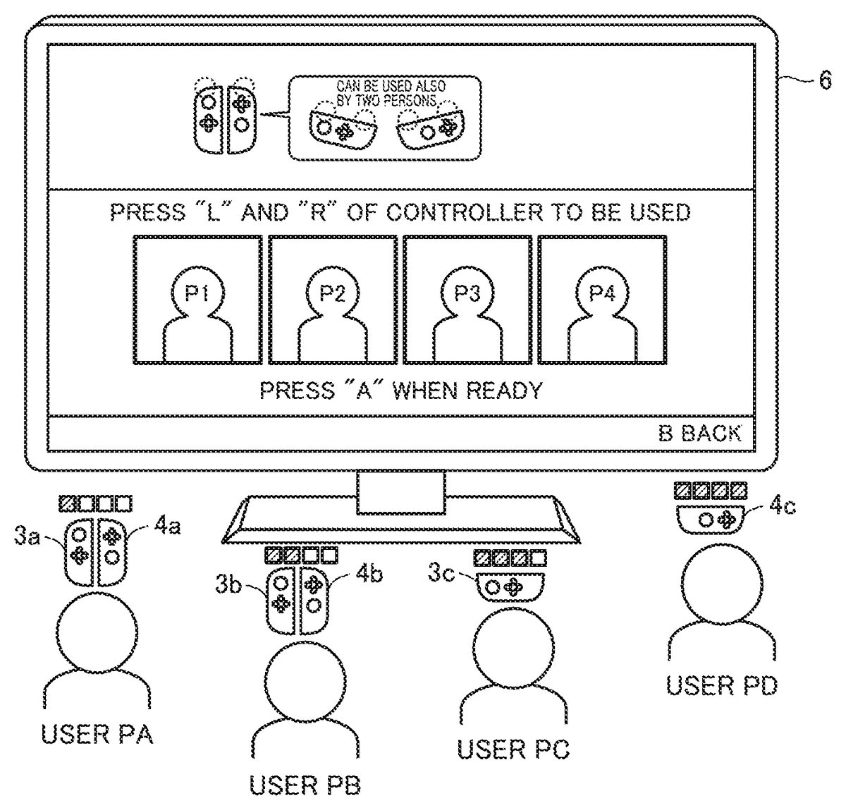
FIGS. 14A and 14Bare example non-limiting diagrams showing examples illustrating a controller registration screen displayed by game device1based on an embodiment.
As shown inFIGS. 14A and 14B, controllers held by users PA to PD representing four players are registered in a controller registration screen shown on television6. In the present example, main body apparatus2registers a controller with which pairing has been completed.
The controller registration screen represents one example of a screen shown when controller registration is indicated in a home menu. The home menu is provided to allow launch of a game application together with various types of setting (controller registration). For example, an icon for launching a game application is provided, and a game application is launched by selecting the icon. An icon for registering a controller is also provided. An application for controller registration processing is launched by selecting the icon and the controller registration screen is shown.
An instruction for registration of a controller can be given also from each game application, and in that case, a manner of an available controller is shown depending on a game application. Since an instruction for registration of a controller can also be given from each game application, it is not necessary to perform a bothersome procedure for performing setting processing by returning to the home menu, and hence usability can be improved.
Television6in the present example inFIG. 14Ashows a message that “press ‘L’ and ‘R’ of controller to be used.” In the present example, each user is invited to press the L button and the R button in registration of a controller held by each user.
Through a series of processes in response to pressing, a player number is registered for a controller of each user. One operation scheme is set in a controller adapted to a plurality of operation schemes.
In the present example, any of an operation scheme in vertical holding of two controllers and an operation scheme in lateral holding of one controller representing a plurality of operation schemes is set. For example, in specifying an operation scheme, an operation scheme may be specified based on whether two controllers or one controller are/is held, or an operation scheme can also be specified based on whether the controller is held vertically or laterally.
A controller can be registered in accordance with such a message.
A state that a controller has not been registered is shown. A player number is allocated as a controller is registered. Then, a manner of a registered controller corresponding to the allocated player number is schematically shown in areas from P1to P4corresponding to player numbers.
A manner of a controller which can be registered is shown in an upper area of the controller registration screen. Registration of two controllers of left controller3and right controller4and registration of one controller, that is, left controller3or right controller4, are shown.
When two controllers are registered, in order to show a position of a button to be selected, together with an image of two controllers, the position is shown as being emphasized with a circular image being added. Possibility of use of two controllers by two persons is also shown. In registration of one controller, in order to show a position of a button to be selected, together with an image of one controller, the position is shown as being emphasized with a circular image being added.
A user can register a controller in a more simplified manner by checking on the controller registration screen, a position of the button emphasized by the circular image, together with the image of the controller.
By way of example, user PA holds left controller3aand right controller4a. User PB holds left controller3band right controller4b. User PC holds a left controller3c. User PD holds a right controller4c.
When user PA registers two controllers, the user presses first L button38provided in left controller3aand first R button60provided in right controller4a.
When user PB registers two controllers, the user presses first L button38provided in left controller3band first R button60provided in right controller4b.
When user PC registers one controller with left controller3c, the user presses second L button43and second R button44provided in left controller3c.
When user PD registers one controller with right controller4c, the user presses second L button65and second R button66provided in right controller4c.
Game device1receives operation data transmitted from each controller, allocates a player number to each controller based on the received operation data, and registers an operation scheme in registration information as necessary.
FIG. 14Bshows an example in which a controller is registered in accordance with operation data.
Specifically, an image of two controllers held by user PA is shown as the controller to which a player number P1is to be allocated.
An image of two controllers held by user PB is shown as the controller to which a player number P2is to be allocated.
An image of one controller held by user PC is shown as the controller to which a player number P3is to be allocated.
A state that a player number P4has not yet been registered (an area shown with a dotted line) is shown.
In the present example, a check image is shown in an area for player number P4which has not yet been registered. In the check image, an image of a controller representing an operation scheme in lateral holding and an image of a controller representing an operation scheme in vertical holding are alternately shown.
By showing the image of two controllers for which the operation scheme in vertical holding has been registered and an image of one controller for which the operation scheme in lateral holding has been registered, difference in manner of a method of operation of the controller is clearly shown and hence usability is improved. By further showing a name and a function of a button of the controller for which the operation scheme in vertical holding has been registered together with the image, information on the method of operation may be presented. By further showing a name and a function of a button of the controller for which the operation scheme in lateral holding has been registered together with the image, information on the method of operation may be presented.
FIG. 15is an example non-limiting diagram illustrating one example of registration information based on the embodiment.
As shown inFIG. 15, registration information include number information, identification information, information associated with wireless communication information, a player number, and information on an operation scheme. The number information is represented by a number provided to a registered controller.
The identification information is information representing a value (for example, an ID) specifically provided to a controller. A controller can uniquely be identified based on the identification information.
In the present embodiment, the identification information includes information indicating whether a controller is the left controller or the right controller. Main body apparatus2can determine based on the identification information provided to the controller whether the controller is the left controller or the right controller. In another embodiment, the identification information does not have to include information indicating whether the controller is the left controller or the right controller. The registration information may include (separately from the identification information) information indicating whether a controller is the left controller or the right controller.
The wireless communication information indicates whether connection setting (that is, pairing) in connection with wireless communication with main body apparatus2has been made. When pairing between main body apparatus2and a controller has been completed, information indicating “set” is stored as wireless communication information associated with the controller. When pairing between main body apparatus2and a controller has not been completed, information indicating “not set” is stored as wireless communication information associated with the controller. Main body apparatus2may store information on connection setting for wireless communication (separately from the registration information), and does not have to carry out pairing again with the controller with which pairing has once been done.
In the present example, main body apparatus2registers a paired controller.
A player number represents identification information specifying a player operated in an application. The player number may be allocated in the order of registration of players or randomly by way of example.
Information on the operation scheme represents information indicating a selected operation scheme when selection from among a plurality of operation schemes can be made for a controller. For left controller3and right controller4in the present example, an operation in vertical holding and an operation in lateral holding representing a plurality of operation schemes can be selected as described with reference toFIGS. 10 and 11.
Some of registration information may be deleted or changed in accordance with an instruction from a user. For example, main body apparatus2may delete information on a designated controller and change information on a number provided to the controller, a player number, and an operation scheme in accordance with an instruction from a user.
A functional block configuration of main body apparatus2based on the embodiment will now be described.
FIG. 16is an example non-limiting diagram illustrating a functional block configuration of main body apparatus2based on the embodiment.
Referring toFIG. 16, a game processing execution module302, a registration processing module304, and a communication control module310are implemented by execution of a program by CPU81of main body apparatus2.
A program implementing the functional block is read, for example, from flash memory84of main body apparatus2or a memory card attached to the first slot, saved in DRAM85, and executed.
Communication control module310makes setting (also called pairing) for wireless communication between main body apparatus2and a controller.
Communication control module310determines whether or not pairing has been completed through wireless communication with a controller. When it is determined through wireless communication with the controller that pairing has not been completed, the communication control module performs pairing processing for wireless communication with the controller and obtains identification information of the controller. Then, communication control module310has the memory register necessary registration information. Specifically, the registration information stored in the memory is updated so as to add number information, identification information, and wireless communication information of the controller in association with the registration information. For number information, for example, information indicating a number which has not been set for another registered controller is set. Identification information provided to the controller is set. As pairing is completed, information indicating “set” is set.
Communication control module310performs processing for establishing communication connection with the paired controller. After communication connection between communication control module310and the controller is established, processing for registering a player number and an operation scheme is performed.
Registration processing module304performs controller registration processing via communication control module310. Specifically, a player number is registered and updated in the registration information in the flash memory. An operation scheme of the controller is registered as necessary.
Game processing execution module302is a module controlling game processing and successively updates contents of representation on display12in accordance with contents of an operation by a user.
Registration processing module304includes a registration unit305, a first determination unit306, and a second determination unit308.
Registration unit305has the memory register a predetermined operation scheme as the registration information as necessary based on a result of determination by first determination unit306or second determination unit308.
First determination unit306determines whether or not operation data received from a controller with which communication connection has been established satisfies a predetermined condition.
An example of the predetermined condition includes whether or not the operation data has second L button and second R button operation data.
When it is determined that the predetermined condition is satisfied or when determination as OK is made (a result of determination is affirmative), registration unit305has the operation scheme in lateral holding registered in the registration information as an operation scheme of the controller.
Another example of the predetermined condition is determination as to whether or not first L button operation data and first R button operation data have simultaneously been received.
When it is determined that the predetermined condition is satisfied or when determination as OK (a result of determination is affirmative), registration unit305has the operation scheme in vertical holding registered in the registration information as an operation scheme of the controller.
Second determination unit308determines whether or not operation data received from a controller with which communication connection has not been established satisfies a predetermined condition.
Second determination unit308includes a time request unit307and a time determination unit309.
Time request unit307requests a controller of transmission of information on an operation time. In response to the request, the controller transmits information on the operation time.
Time determination unit309obtains transmitted information on the operation time and determines whether or not an operation of the controller satisfies a predetermined condition.
Specifically, second determination unit308determines whether or not operations onto second L button43and second R button44have substantially simultaneously been performed in left controller3. Second determination unit308determines whether or not operations onto second L button65and second R button66have substantially simultaneously been performed in right controller4. By way of example of a determination scheme, whether or not a time difference between two pieces of information on operation times is within a predetermined period is determined based on the information on the operation time. When it is determined that the time difference between the two pieces of information on the operation times is within the predetermined period, determination as OK is made. When it is determined that the time difference between the two pieces of information on the operation times is not within the predetermined period, determination as NG is made.
When determination as OK (a result of determination is affirmative) is made based on a result of determination by second determination unit308, registration unit305registers a predetermined scheme as the operation scheme of the controller. In the present example, registration unit305registers the operation scheme in lateral holding in the registration information.
FIG. 17is an example non-limiting flowchart illustrating processing for transmission of data on left controller3based on the embodiment.
Processing in each step in the flowchart shown inFIG. 17is merely by way of example. So long as similar results can be obtained, an order of processing in the steps may be changed or another processing may be performed in addition to (or instead of) processing in each step.
Referring toFIG. 17, communication control unit101of left controller3determines whether or not operation button group103has been operated (step ST0).
When communication control unit101determines in step ST0that operation button group103has been operated (YES in step ST0), it determines whether or not communication connection with main body apparatus2has been established (step ST1).
When communication control unit101determines in step ST0that operation button group103has not been operated (NO in step ST0), the state in step ST0is maintained.
When communication control unit101determines in step ST1that communication connection with main body apparatus2has been established (YES in step ST1), it transmits operation data to main body apparatus2(step ST2). The operation data includes identification information data and information on an operated button.
Then, the process ends (end).
When communication control unit101determines in step ST1that communication connection with main body apparatus2has not been established (NO in step ST1), it transmits a connection request for establishing communication connection to main body apparatus2(step ST3).
Then, communication control unit101has memory102store operation information resulting from an operation of operation button group103(step ST4). Together with the information on the operated operation button, information on time obtained by timer46at which the operated operation button has been operated is stored in memory102.
Then, the process ends (end).
Though left controller3has been described in the present example, the description is applicable also to right controller4.
In the present example, communication control unit101has memory102store operation information when communication connection is not established. Operation information may be stored in memory102also when communication connection is established.
FIGS. 18A and 18Bare example non-limiting diagrams illustrating operation data transmitted from the controller based on the embodiment to main body apparatus2.
FIG. 18Ashows operation data500transmitted from controller3by way of example. Operation data500includes identification information data501, second L button operation data502, and second R button operation data503.
By way of example, second L button operation data502and second R button operation data503are operation data resulting when a user presses both of second L button43and second R button44provided in controller3.
Though operation data of left controller3is described, operation data of right controller4is basically also similar. In the case of operation data of right controller4, second L button operation data502and second R button operation data503are operation data resulting when a user presses both of second L button65and second R button66provided in right controller4.
FIG. 18Bshows operation data510and520transmitted from left controller3and right controller4, respectively, by way of example.
Operation data510includes identification information data512and first L button operation data514.
Operation data520includes identification information data522and first R button operation data524.
By way of example, first L button operation data514is operation data resulting when a user presses first L button38provided in left controller3. First R button operation data524is operation data resulting when a user presses first R button60provided in right controller4.
In the controller registration screen described with reference toFIGS. 14A and 14B, by way of example, when user PC presses second L button43and second R button44provided in left controller3c, operation data described with reference toFIG. 18Ais transmitted to main body apparatus2. First determination unit306of registration processing module304determines whether or not the received operation data includes the second L button and second R button operation data. Registration unit305registers the operation scheme in lateral holding in the registration information based on a result of determination by first determination unit306.
In the controller registration screen described with reference toFIGS. 14Aand14B, by way of example, when user PA presses first L button38provided in left controller3aand first R button60provided in right controller4a, operation data described with reference toFIG. 18Bis transmitted to main body apparatus2. First determination unit306of registration processing module304determines whether or not the first L button operation data and the first R button operation data have simultaneously been received. Registration unit305registers the operation scheme in vertical holding in the registration information based on a result of determination by first determination unit306.
FIGS. 19A and 19Bare example non-limiting diagrams illustrating operation information stored in memory102based on the embodiment.
FIG. 19Ashows storage of data corresponding to two operations as operation information.
By way of example, while communication connection with main body apparatus2has not been established, an operation onto second L button43and second R button44is performed. The operation is registered in association with time.
FIG. 19Bshows storage of data corresponding to one operation as operation information.
By way of example, while communication connection with main body apparatus2has not been established, an operation onto first L button38is performed. The operation is registered here again in association with time.
The operation information is used for determination processing in second determination unit308.
FIG. 20is an example non-limiting flowchart illustrating one example of a flow of processing for registration of a controller with which communication connection has not been established, the processing being performed in main body apparatus2based on the embodiment.
Processing in each step in the flowchart shown inFIG. 20is merely by way of example. So long as similar results can be obtained, an order of processing in the steps may be changed or another processing may be performed in addition to (or instead of) processing in each step. Though processing in each step in the flowchart is described as being performed by CPU81of main body apparatus2in the present embodiment, processing in some steps in the flowchart may be performed by a processor or a dedicated circuit other than CPU81. A part of processing performed in main body apparatus2may be performed by another information processing apparatus which can communicate with main body apparatus2(for example, a server which can communicate with main body apparatus2through a network). Each processing shown inFIG. 20may be performed by cooperation of a plurality of information processing apparatuses including main body apparatus2.
Referring toFIG. 20, CPU81determines whether or not there is a request for connection of a controller (step S2). CPU81determines whether or not it has received a connection request from a controller with which communication connection has not been established.
When CPU81determines that it has received a request for connection of a controller (YES in step S2), it performs connection processing (step S4).
Specifically, when it is determined that communication connection with a controller has not been established, communication control module310performs processing for establishing communication connection between main body apparatus2and a controller (communication connection processing).
Then, CPU81requests for an elapsed time (step S6). Communication control module310notifies second determination unit308of registration processing module304of completion of communication connection processing. Time request unit307of second determination unit308requests the controller with which communication connection processing has been completed of transmission of information on an operation time.
FIG. 21is an example non-limiting flowchart illustrating transmission of an elapsed time by the controller based on the embodiment.
Processing in each step in the flowchart shown inFIG. 21is merely by way of example. So long as similar results can be obtained, an order of processing in the steps may be changed or another processing may be performed in addition to (or instead of) processing in each step.
Referring toFIG. 21, communication control unit101of left controller3determines whether or not it has received a request for an elapsed time (step ST10).
When communication control unit101determines in step ST10that it has received a request for an elapsed time (YES in step ST10), it checks operation information (step ST12). Specifically, communication control unit101checks information on a time at which the operation button has been operated which is stored in memory102.
Then, communication control unit101calculates an elapsed time (step ST14). Specifically, communication control unit101calculates the elapsed time by comparing the time of reception of the request for the elapsed time with the time of an operation of the operation button stored in memory102. As shown inFIG. 19A, when information on a plurality of operation times which correspond to the operation data resulting from pressing of both of second L button43and second R button44is stored in memory102, the elapsed time is calculated for each of them.
Then, communication control unit101transmits the elapsed time to main body apparatus2(step ST16). Communication control unit101transmits data on the calculated elapsed time to main body apparatus2.
Then, the process ends (end).
When communication control unit101determines in step ST10that it has not received a request for the elapsed time (NO in step ST10), the state in step ST10is maintained.
Though left controller3has been described in the present example, the description is applicable also to right controller4.
Referring again toFIG. 20, CPU81then determines whether or not it has received data (step S8). Communication control unit310determines whether or not it has received data from the controller.
When CPU81determines in step S8that it has received data (YES in step S8), it performs determination processing (step S10). Details of the determination processing will be described later. When communication control module310determines that it has received the data, it outputs the data to time determination unit309of second determination unit308.
Then, CPU81determines whether or not determination as OK is made (step S12). Registration unit305determines whether or not determination as OK is made, as a result of determination by second determination unit308.
When CPU81determines in step S12that determination as OK is made (YES in step S12), a player number is registered (step S14). Specifically, registration unit305registers a player number in registration information. A player number is registered in the order of registration of players. Player numbers are registered in such a manner that a first player is registered as P1, a second player is registered as P2, and so on. Then, CPU81registers the operation scheme in lateral holding in the registration information (step S16). Specifically, registration unit305registers information indicating the operation scheme in lateral holding in a field of the operation scheme in the registration information.
When CPU81determines in step S12that determination as NG is made (NO in step S12), it has a check image shown (step S2). As described above, registration unit305has the check image shown. Registration unit305has the controller registration screen as described with reference toFIG. 14Bshown.
Then, CPU81determines whether or not it has received operation data (step S24). Specifically, communication control module310determines whether or not it has further received operation data from the controller. CPU81maintains the state in step S24until it receives operation data.
When CPU81determines in step S24that it has received operation data (YES in step S24), the process proceeds to next step S26. Since operation data is received from a controller with which communication connection has been established, determination processing in first determination unit306is performed.
CPU81determines whether or not operation data has second L button and second R button operation data (step S26). Specifically, first determination unit306determines whether or not the operation data has second L button and second R button operation data.
Then, when CPU81determines that the operation data has second L button and second R button operation data (YES in step S26), a player number is registered for one controller (step S14). Specifically, registration unit305registers a player number in the registration information. A player number is registered in the order of registration of players. Player numbers are registered in such a manner that a first player is registered as P1, a second player is registered as P2, and so on. Then, CPU81registers the operation scheme in lateral holding in the registration information (step S16). Specifically, registration unit305registers information indicating the operation scheme in lateral holding in a field of the operation scheme in the registration information.
Then, CPU81updates the controller registration screen (step S18). Specifically, registration unit305has an image of the controller set in accordance with the order of registration of the player shown. For example, when a third player number is registered, the left controller operated as being laterally oriented is shown in an area third from the left in the controller registration screen. An indicator image indicating the third player number is shown as an indicator image. A notification LED in the corresponding left controller may be turned on in correspondence with the player number.
When CPU81determines in step S26that the operation data does not have second L button and second R button operation data (NO in step S26), CPU81determines whether or not first L button operation data and first R button operation data have been simultaneously received (step S28). Specifically, as described with reference toFIG. 18B, first determination unit306determines whether or not one of a plurality of pieces of simultaneously received operation data includes first L button operation data and the other operation data includes first R button operation data.
When CPU81determines in step S28that first L button operation data and first R button operation data have been simultaneously received (YES in step S28), a player number is registered for two controllers constituting a set (step S30). Specifically, registration unit305registers the player number in the registration information. The player number is registered for each of two controllers in accordance with the order of registration of the players. Player numbers are registered in such a manner that a first player is registered as P1, a second player is registered as P2, and so on.
In the present example, left controller3and right controller4constitute a set. Therefore, two left controllers or two right controllers do not constitute a set. Simultaneous reception of operation data is not limited to exactly the same timing of reception, and encompasses also an example where a period until reception of subsequent operation data after reception of first operation data is extremely short.
Then, CPU81registers the operation scheme in vertical holding in the registration information (step S32). Specifically, registration unit305registers information indicating the operation scheme in vertical holding in a field of the operation scheme in the registration information.
Then, CPU81updates the controller registration screen (step S18). Specifically, registration unit305has an image of a controller set in accordance with the order of registration of players shown. For example, when a first player number is registered, the left controller and the right controller operated as being vertically held are shown in an area first from the left in the controller registration screen. An indicator image indicating the first player number is shown as an indicator image. Notification LEDs in a left controller and a right controller corresponding to the player number may be turned on in correspondence with the player number.
Since subsequent processing is the same, detailed description thereof will not be repeated.
When CPU81determines in step S28that the first L button operation data and the first R button operation data have not been simultaneously received (NO in step S28), the process proceeds to step S20.
In step S20, CPU81determines whether or not controller registration processing has ended (step S20). Specifically, when the “A” button is selected in the controller registration screen described with reference toFIGS. 14A and 14B, registration unit305determines that controller registration processing has ended.
When CPU81determines in step S20that controller registration processing has ended (YES in step S20), the process ends (end).
When CPU81determines that controller registration processing has not ended (NO in step S20), the process returns to step S2and the process is repeated.
FIG. 22is an example non-limiting flowchart illustrating a sub routine of determination processing performed in main body apparatus2based on the embodiment. The determination processing is processing in time determination unit309.
As shown inFIG. 22, CPU81determines whether or not it has received a plurality of pieces of data on an elapsed time (step S110). Time determination unit309determines whether or not the received data includes a plurality of pieces of data on an elapsed time.
Then, when CPU81determines in step S110that it has received a plurality of pieces of data on an elapsed time (YES in step S110), it determines whether or not a plurality of elapsed times are substantially the same (step S112). When time determination unit309determines that the received data includes a plurality of pieces of data on an elapsed time, it determines whether or not the pieces of data on an elapsed time have substantially the same value. Specifically, time determination unit309determines whether or not a time difference between two pieces of data on an elapsed time is within a predetermined period.
Then, when CPU81determines that the plurality of elapsed times are substantially the same (YES in step S112), it makes determination as OK (step S14). When time determination unit309determines that the pieces of data on an elapsed time have substantially the same value, it outputs determination as OK to registration unit305.
Then, the process ends (return).
When CPU81determines in step S110that it has not received a plurality of pieces of data on an elapsed time (NO in step S110) or when it determines that the plurality of elapsed times are not substantially the same, it makes determination as NG (step S116). When time determination unit309determines that the pieces of data on an elapsed time do not have substantially the same value, it outputs determination as NG to registration unit305.
Then, the process ends (return).
FIG. 23is an example non-limiting sequence diagram illustrating transmission and reception of data between controller3and main body apparatus2based on the embodiment. In the present example, communication connection between controller3and main body apparatus2has not been established.
As shown inFIG. 23, a user operates second L button43and second R button44of controller3(sequence sq2).
Then, controller3checks whether or not communication connection has been established (sequence sq3). In the present example, communication connection has not been established.
Then, controller3transmits a connection request to main body apparatus2(sequence sq4).
Controller3has memory102store operation information (sequence sq6).
Main body apparatus2receives the connection request transmitted from controller3(sequence sq8).
Main body apparatus2starts processing for communication connection with controller3in response to the connection request (sequence sq12).
Main body apparatus2notifies controller3of approval for connection (sequence sq14).
Controller3receives the notification about approval for connection from main body apparatus2(sequence sq16).
Then, controller3transmits a response signal to main body apparatus2(sequence sq18).
Main body apparatus2receives the response signal from controller3(sequence sq20).
Processing for communication connection between controller3and main body apparatus2is thus completed (sequence sq22).
Then, main body apparatus2requests controller3with which communication connection has been established of transmission of an elapsed time relating to an operation time (sequence sq24).
Then, controller3receives the request for an elapsed time from main body apparatus2(sequence sq26).
Then, controller3checks operation information stored in memory102(sequence sq28).
Then, controller3calculates an elapsed time (sequence sq30).
Controller3transmits the elapsed time to main body apparatus2(sequence sq32).
Main body apparatus2receives the elapsed time transmitted from controller3(sequence sq34).
Main body apparatus2determines whether or not it has received a plurality of pieces of data on the elapsed time, and when it determines that it has received the plurality of pieces of data on the elapsed time, it determines whether or not the pieces of data on the elapsed time have substantially the same value (sequence sq36).
In the present example, main body apparatus2determines that the plurality of elapsed times are substantially the same and makes determination as OK (sequence sq38).
Main body apparatus2has the operation scheme in lateral holding registered in the registration information (sequence sq40).
Through the processing, in controller registration processing for a controller with which communication connection has not been established, by operating once a controller before communication connection therewith is established, an operation scheme can readily be registered based on information on an operation time along with communication connection processing, and hence usability can be improved.
In the present example, a scheme for controller3to calculate an elapsed time in response to a request for an elapsed time from main body apparatus2and to transmit the calculated elapsed time to main body apparatus2and for main body apparatus2to determine whether or not pieces of data on an elapsed time have substantially the same value has been described. Instead of controller3calculating an elapsed time, main body apparatus2may calculate an elapsed time. Specifically, controller3may transmit operation information (including an operation time) stored in memory102to main body apparatus2in response to a request and main body apparatus2may calculate an elapsed time and determine whether or not pieces of data on the elapsed time have substantially the same value.
Under the scheme above, the controller determines whether or not communication connection with main body apparatus2has been established, when communication connection has been established, it transmits operation data, and when communication connection has not been established, it transmits a connection request. Main body apparatus2, however, may determine whether or not communication connection has been established. In this case, the controller constantly transmits operation data in response to an operation of an operation button. When communication connection has not been established, main body apparatus2may perform communication connection processing based on the operation data.
Controller registration processing can be performed based on operation data transmitted from each controller. In controller registration processing, one operation scheme can be registered based on contents in operation data for a controller for which selection from among a plurality of operation schemes can be made. Thus, controller registration processing in connection with an operation scheme can readily be performed and usability can be improved.
In the controller registration processing, an operation scheme once registered can also be changed.
For example, after the operation scheme in vertical holding in which two controllers are used is registered, change to the operation scheme in lateral holding in which one controller is used can also be made.
Specifically, both of the second L button and the second R button are pressed in left controller3of two controllers registered in association with player number P1. Through the processing, operation data is transmitted from the left controller to main body apparatus2.
Main body apparatus2receives the operation data and performs processing for registering again a player and processing for registering lateral holding. The operation scheme of left controller3registered in association with player number P1is changed to the operation scheme in lateral holding while the player number in the registration information is maintained. Information on allocation of the player number and the operation scheme in the registration information is deleted for right controller4registered in association with player number P1. Though description has been given for left controller3, the description is also applicable to right controller4, and processing for registering again of a player and for registering lateral holding is performed under a similar scheme.
After the operation scheme in lateral holding in which one controller is used is registered, change to the operation scheme in vertical holding in which two controllers are used can also be made.
Specifically, both of the first L button in left controller3registered in association with player number P3and the first R button in right controller4registered in association with player number P4are pressed. Through the processing, operation data is transmitted from left controller3and right controller4to main body apparatus2.
Main body apparatus2receives the operation data and performs processing for registering again a player and processing for registering vertical holding under the scheme described above.
Left controller3registered in association with player number P3and right controller4registered in association with player number P4are determined as controllers constituting a set. The operation scheme of left controller3registered in association with player number P3in the registration information is changed to the operation scheme in vertical holding while the player number is maintained. The player number of right controller4registered in association with player number P4is changed to player number P3and an operation scheme thereof is changed to the operation scheme in vertical holding.
[G. Game Processing]
FIG. 24is an example non-limiting diagram of one example illustrating game processing performed by game device1based on the embodiment.
InFIG. 24, an image generated by game device1is shown on television6.
In the present example, four players are shown. User PA operates a corresponding object with two controllers3aand4a. User PB operates a corresponding object with two controllers3band4b. User PC operates a corresponding object with one controller3c. User PD operates a corresponding object with one controller4c.
In the present example, game device1divides a display area of television6into four sections, and shows an image for user PA (for example, an image including the first object) in a divided display area6A and an image for user PB (for example, an image including the second object) in a divided display area6B. Similarly, game device1shows an image for user PC (for example, an image including a third object) in a divided display area6C and an image for user PD (for example, an image including a fourth object) in a divided display area6D.
Each controller controls a notification LED based on a player number from game device1.
In the present example, users PA to PD representing four players operate corresponding objects with the controllers, respectively. This is also applicable to an example in which there is one player.
[H. Processing Procedure]
A processing procedure involved with game processing in game device1based on the embodiment will now be described.
FIG. 25is an example non-limiting flowchart showing a processing procedure involved with the game processing based on the embodiment.
Each step shown inFIG. 25is typically performed by execution of a program by CPU81of main body apparatus2.
Referring toFIG. 25, CPU81determines whether or not start of game processing has been indicated (step S50). Game processing execution module302determines whether or not start of game processing has been indicated.
When CPU81determines that start of game processing has been indicated (YES in step S50), it generates a game image in which an object is arranged in a game space (step S51). Game processing execution module302generates a game image in which an object is arranged in a game space based on a program saved and executed in DRAM85.
Then, CPU81determines whether or not it has obtained operation data (step S52). Specifically, game processing execution module302determines whether or not operation data has been obtained through communication control module310.
When CPU81determines in step S52that it has obtained operation data (YES in step S52), it determines whether or not an operation in lateral holding has been registered (step S54). Specifically, game processing execution module302determines whether or not the operation scheme in lateral holding has been registered in the information on the operation scheme in the registration information for a controller corresponding to the obtained operation data, by referring to the registration information stored in flash memory84.
When CPU81determines in step S54that the operation in lateral holding has not been registered (NO in step S54), it performs processing based on the operation data (step S56). Specifically, when game processing execution module302determines that the operation scheme in lateral holding has not been registered in the information on the operation scheme in the registration information for the controller corresponding to the obtained operation data by referring to the registration information stored in flash memory84, it performs game processing based on the obtained operation data.
Then, CPU81updates the game image (step S58). Specifically, game processing execution module302generates a game image in accordance with the operation data in accordance with an obtained operation by a user. Then, updated output is given to television6in accordance with the generated game image.
Then, CPU81determines whether or not end of game processing has been indicated (step S60).
When CPU81determines in step S60that end of game processing has been indicated (YES in step S60), the process ends (end).
When CPU81determines in step S60that end of game processing has not been indicated (NO in step S60), the process returns to step S52and the process is repeated.
When CPU81determines in step S54that the operation in lateral holding has been registered (YES in step S54), it performs processing for converting operation data into converted operation data (step S62). Specifically, when game processing execution module302determines that the operation scheme in lateral holding has been registered in the information on the operation scheme in the registration information for the controller corresponding to the obtained operation data by referring to the registration information stored in flash memory84, it performs processing for converting the operation data into converted operation data.
Specifically, in the case of left controller3, conversion to such converted operation data that a direction instruction from analog stick32is rotated counterclockwise by 90° is made.
Thus, an instruction from left controller3operated as being laterally held onto an object can be the same in direction as a direction instruction from analog stick32of left controller3operated as being vertically held. Functions of four operation buttons33to36are allocated to the X button, the A button, the Y button, and the B button, respectively. Thus, the operation buttons in left controller3operated as being laterally held for an object can be the same in function as four operation buttons33to36under the operation scheme in vertical holding.
In the case of right controller4, conversion to such converted operation data that a direction instruction from analog stick52is rotated clockwise by 90° is made.
Thus, an instruction from right controller4operated as being laterally held onto an object can be the same in direction as a direction instruction from analog stick52of right controller4operated as being vertically held. Functions of four operation buttons53to56are allocated to the B button, the Y button, the A button, and the X button, respectively. Thus, the operation buttons in right controller4operated as being laterally held for an object can be the same in function as four operation buttons53to56under the operation scheme in vertical holding.
Then, CPU81performs processing based on the converted operation data (step S64). Specifically, game processing execution module302generates a game image in accordance with the converted operation data. Then, updated output is given to television6in accordance with the generated game image.
Since subsequent processing is similar, detailed description thereof will not be repeated.
Then, CPU81updates the game image (step S58). Specifically, game processing execution module302generates a game image in accordance with operation data in accordance with an obtained operation by a user. Then, updated output is given to television6in accordance with the generated game image.
Since subsequent processing is similar, detailed description thereof will not be repeated.
An application executable on a personal computer may be provided as a program in the present embodiment. The program according to the present embodiment may be incorporated as some functions of various application programs executed on the personal computer.
While certain example systems, methods, devices, and apparatuses have been described herein, it is to be understood that the appended claims are not to be limited to the systems, methods, devices, and apparatuses disclosed, but on the contrary, are intended to cover various modifications and equivalent arrangements included within the spirit and scope of the appended claims.
Claims
- A game system comprising: a game controller;and a main body apparatus, the game controller having a first operation member, a second operation member, a memory storing a first operation time at which the operation onto the first operation member has been performed and a second operation time at which the operation onto the second operation member has been performed, and a first control circuit transmitting to the main body apparatus, a connection signal in accordance with at least any of an operation onto the first operation member and an operation onto the second operation member, the main body apparatus having a second control circuit, wherein the second control circuit performs processing for establishing connection with the game controller in accordance with the connection signal, and transmits to the game controller, a request signal requesting for information on the first operation time and the second operation time stored in the memory when the processing for establishing connection is completed, the first control circuit of the game controller transmits the information on the first operation time and the second operation time stored in the memory to the main body apparatus in response to the request signal, and the second control circuit of the main body apparatus determines whether the operation onto the first operation member and the operation onto the second operation member satisfy a predetermined condition based on the information on the first operation time and the second operation time, and registers a first operation scheme as an operation scheme of the game controller when a result of determination is affirmative.
- The game system according to claim 1 , wherein the second control circuit determines whether the operation onto the first operation member and the operation onto the second operation member have been performed substantially simultaneously based on the information on the first operation time and the second operation time.
- The game system according to claim 1 , wherein the second control circuit performs game processing based on at least any of a first operation signal in accordance with the operation onto the first operation member and a second operation signal in accordance with the operation onto the second operation member.
- The game system according to claim 1 , wherein the second control circuit registers the first operation scheme among a plurality of operation schemes as the operation scheme of the game controller when the result of determination is affirmative.
- The game system according to claim 1 , wherein the first and second operation members are on a side of a predetermined operation surface of a housing of the game controller when a user performs an operation.
- The game system according to claim 1 , wherein the second control circuit registers, when a result of determination is negative, the first operation scheme as the operation scheme of the game controller based on a first operation signal in accordance with the operation onto the first operation member and a second operation signal in accordance with the operation onto the second operation member which are subsequently received.
- The game system according to claim 1 , wherein the game controller further includes a third operation member, the first control circuit transmits to the main body apparatus, a third operation signal in accordance with an operation onto the third operation member, and the second control circuit registers, when a result of determination is negative, a second operation scheme different from the first operation scheme as the operation scheme of the game controller based on the third operation signal which is subsequently received.
- A game controller which can communicate with a main body apparatus comprising: a first operation member;a second operation member;a memory storing a first operation time at which the operation onto the first operation member has been performed and a second operation time at which the operation onto the second operation member has been performed;and a control circuit;wherein the control circuit starts processing for establishing connection with the main body apparatus by transmitting to the main body apparatus, a connection signal in accordance with at least any of an operation onto the first operation member and an operation onto the second operation member, receives a request signal indicating a request for a first elapsed time since the operation onto the first operation member and a second elapsed time since the operation onto the second operation member from the main body apparatus with which the processing for establishing connection has been completed, in order for the main body apparatus to detect simultaneous pressing of the first operation member and the second operation member, transmits to the main body apparatus, in response to the request signal, the first elapsed time based on a current time and the first operation time stored in the memory and the second elapsed time based on the current time and the second operation time stored in the memory, and transmits to the main body apparatus, a first operation signal in accordance with the operation onto the first operation member and a second operation signal in accordance with the operation onto the second operation member for game processing in the main body apparatus.
- The game controller according to claim 8 , wherein the first and second operation members are provided on a side of a predetermined operation surface of a housing of the game controller when a user performs an operation.
- A game system comprising: a game controller;and a main body apparatus, the game controller having a first operation member, a second operation member, a memory storing a first operation time at which an operation onto the first operation member has been performed and a second operation time at which an operation onto the second operation member has been performed when the operation onto the first operation member and the operation onto the second operation member have been performed while connection with the main body apparatus has not been established, and a first control circuit transmitting to the main body apparatus, a connection signal for connection with the main body apparatus while connection with the main body apparatus has not been established, the main body apparatus having a second control circuit, wherein the second control circuit performs processing for establishing connection with the game controller in accordance with the connection signal, and transmits to the game controller, a request signal requesting for information on the first operation time and the second operation time stored in the memory when the processing for establishing connection is completed, the first control circuit of the game controller transmits the information on the first operation time and the second operation time stored in the memory to the main body apparatus in response to the request signal, and the second control circuit of the main body apparatus determines whether the operation onto the first operation member and the operation onto the second operation member satisfy a predetermined condition based on the information on the first operation time and the second operation time, and registers a first operation scheme as an operation scheme of the game controller when a result of determination is affirmative.
Disclaimer: Data collected from the USPTO and may be malformed, incomplete, and/or otherwise inaccurate.