U.S. Pat. No. 10,080,956
Detecting the Changing Position Of A Face To Move And Rotate A Game Object In A Virtual Environment
AssigneeBALLCRAFT LLC
Issue DateSeptember 4, 2015
Illustrative Figure
Abstract
Methods for a mobile device with a front facing camera to use the detected position of the user's face as a game controller as well as a method of displaying the live streaming face within the video with audio within a virtual environment. Using a reference frame which serves as the origin, the subsequent frames of the live streaming video are used to calculate the change in position of the face detected within the video frame, and calculations of position, rotation, speed and distance are used to position a game object. Additionally this is a method for having a live video stream with live audio textured onto 2D/3D objects within a virtual environment with only the perspective cropped face displayed. This provides the appearance of the face as stable and unmoving even when the device's camera and/or user's face are moving relative to each other.
Description
DETAILED DESCRIPTION OF ILLUSTRATIVE EMBODIMENTS While the invention is susceptible to embodiments in many different forms, there are shown in the drawings and will be described in detail herein the preferred embodiments of the present invention. It should be understood, however, that the present disclosure is to be considered an exemplification of the principles of the invention and is not intended to limit the spirit or scope of the invention and/or claims of the embodiments illustrated. The following descriptions and diagrams and figures describe a method that allows the cropping of the display of the video feed received over the network using the UV coordinates. This method contains a program that can be adapted to any existing face detecting technology that uses any standard or specialized camera for portable and display devices. FIG. 1Describes a common knowledge of the three linear and rotational axes present in any common portable device that exists in the market which are used as reference in both virtual and real worlds. These axes are y or yaw102, x or pitch103and z or roll104axes for linear or rotational movement respectively. FIG. 2illustrates the representation of the portable device shown as202with a front facing camera203. When used with the invention and face detection technology shown in204a rectangular area205will be created containing the video stream of the face of the user206. The detection is regardless of the linear or rotational movement of the portable device shown as207and208respectively, where the movement of the device changes the location of the face within the video stream however, the perspective cropping makes the rendering of the face appear as though the face has not moved within the video stream. FIG. 3302shows a display device with its own camera (embedded or peripheral) that will never move that will use the invention and face ...
DETAILED DESCRIPTION OF ILLUSTRATIVE EMBODIMENTS
While the invention is susceptible to embodiments in many different forms, there are shown in the drawings and will be described in detail herein the preferred embodiments of the present invention. It should be understood, however, that the present disclosure is to be considered an exemplification of the principles of the invention and is not intended to limit the spirit or scope of the invention and/or claims of the embodiments illustrated.
The following descriptions and diagrams and figures describe a method that allows the cropping of the display of the video feed received over the network using the UV coordinates. This method contains a program that can be adapted to any existing face detecting technology that uses any standard or specialized camera for portable and display devices.
FIG. 1Describes a common knowledge of the three linear and rotational axes present in any common portable device that exists in the market which are used as reference in both virtual and real worlds. These axes are y or yaw102, x or pitch103and z or roll104axes for linear or rotational movement respectively.
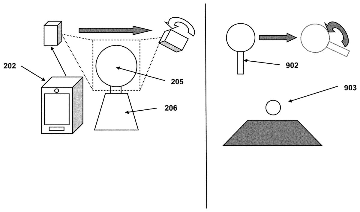
FIG. 2illustrates the representation of the portable device shown as202with a front facing camera203. When used with the invention and face detection technology shown in204a rectangular area205will be created containing the video stream of the face of the user206. The detection is regardless of the linear or rotational movement of the portable device shown as207and208respectively, where the movement of the device changes the location of the face within the video stream however, the perspective cropping makes the rendering of the face appear as though the face has not moved within the video stream.
FIG. 3302shows a display device with its own camera (embedded or peripheral) that will never move that will use the invention and face detection technology described inFIG. 2to calculate the UV points which represent the rectangular area of the user's face regardless of the changing position of the player as described in304as long as the face remains in the field of vision of the camera.
FIG. 4is a visual representation of how the method in this invention is used along with the face detection technology on a standard frame of a video stream402to calculate the UV coordinates404centered on the user's face403. The method only calculates two UV points like405that are enough to create the rectangular area of coordinates.
The two points are transmitted with the video feed in its entirety or cropped to the receiving device that will use these points UV coordinates needed to crop the video stream and apply it as a 2D texture409to a 3D game object408that will be displayed in a virtual environment407displayed on any screen406. Or only the perspective cropped video stream is transmitted and it is applied as a 2D texture409to a 3D game object408that is displayed in a virtual environment407displayed on any screen406.
FIG. 5Displays the flow chart of the use of the perspective cropping and face detection technology to transmit over the network the portion of the images that contain the perspective cropped face. The algorithm that accomplishes this is as follows:
void Update( ){If(profilemode == ProfileMode.Video && mHeadTracker.FaceFound)//when face is detected, transmit video{Quaternion current = GyroUtils.CurrentQuaternion;Quaternion inverseBase = Quaternion.Inverse(GyroUtils.BaseQuaternion);Quaternion compensation = current * inverseBase;videoFeedTexture = ImageCompensator.RotateImage(videoFeed-Texture ,compensation.eulerAngles);videoFeedTexture = mHeadTracker.GetFrameTexture( );mHeadPosition = mHeadTracker.GetHeadCoordinates( );int width = mHeadPosition.xMax − mHeadPosition.xMin;int height= mHeadPosition.yMax − mHeadPosition.yMin;Texture2D croppedImage = new Texture2D(width , height);croppedImage.SetPixels(videoFeedTexture.GetPixels(mHeadPosition.xMin, mHeadPosition.yMin, width , height));croppedImage.Apply( );SendToNetwork(“VideoUpdate”, croppedImage.EncodeToPng( ));}}
mHeadPosition is a structure given to the algorithm that will help determine the size of the rectangular area centered on the user's face that is desired to be used in the virtual environment.
GyroUtils.BaseQuaternion is the reference rotation of the device when the user designates the device to be in the normal and correct position.
FIG. 6Describes the process that obtains the perspective corrected video stream and UV coordinate data and applies it to a 2D texture on any 2D or 3D game object in the virtual world.
void VideoUpdate(byte[ ] videoData){mVideoTexture = new Texure2D( );mVideoTexture.ReadBytes(videoData);mVideoTexture.Apply( );objectRenderer.material.mainTexture = mVideoTexture;}
FIG. 7Displays the flow chart of the use of the face detection technology and perspective correction to calculate the location of the two UV points necessary for cropping. The algorithm that accomplishes this is as follows:
void Update( ){If(profilemode == ProfileMode.Video && mHeadTracker.FaceFound)//when face is detected, transmit video{Quaternion current = GyroUtils.CurrentQuaternion;Quaternion inverseBase = Quaternion.Inverse(GyroUtils.BaseQuaternion);Quaternion compensation = current * inverseBase;videoFeedTexture =ImageCompensator.RotateImage(compensation.eulerAngles);videoFeedData = mHeadTracker.GetFrameData( );mHeadPosition = mHeadTracker.GetHeadCoordinates( );Vector2 uv1 = new Vector2 (mHeadPosition.xMin /Screen.videoFeedTexture ,mHeadPosition.yMin / Screen.videoFeedTexture );Vector2 uv2 = new Vector2 (mHeadPosition.xMax /Screen.videoFeedTexture ,mHeadPosition.yMax / Screen.videoFeedTexture );SendToNetwork(“VideoUpdate”, videoFeedData, uv1, uv2);}}
FIG. 8Describes the process that crops the video stream on the receiving end using the UV points transmitted with the video frame data. The UV points for the rectangular area are calculated and applied on the 2D texture so that the texturing remains centered on the other user's face.
void VideoUpdate(byte[ ] videoData, Vector2 coord1, Vector2 coord2){mVideoTexture = new Texure2D( );mVideoTexture.ReadBytes(videoData);mVideoTexture.Apply( );objectRenderer.mesh.uvs = new Vector2[ ] {coord1, coord2};objectRenderer.material.mainTexture = mVideoTexture;}
FIG. 9Shows a typical case where face tracking is used as a game object controller902in 3D space303by knowing the position and rotation of the face205detected by the front facing camera or a device such as202. Face tracking also detects the depth by using the ratio of the size of the area that contains the face compared to the size of the entire captured frame. This is achieved in both portable devices and static displays.
FIG. 10Displays the flow chart of the use of face tracing technology that uses the portable device's front facing camera to change position and rotation of game objects.
When the face is detected, it is compared to the orientation of the device for rotation calculations, and the size of the face is compared to the size of the captured image frame for depth positioning. The vertical and horizontal positions of the face are obtained based on the pixel positioning of the face area and referenced to the center of the image frame.
When face tracking is used as a game object controller in a virtual environment, the following code controls the panning of a paddle or any 3D object as well as its rotation and distance from the reference frame.
float scaleFactor = 1f;float moveSpeed = 20f;float rotationSpeed = 15f;void Update( ){Vector2 facePosition = −HeadTracker.newPosition * scaleFactor;Vector2 faceSize = HeadTracker.headSize;Vector2 ImageSize = HeadTracker.imageSize;faceSize = faceSize / ImageSize.magnitude; //normalize the sizefloat faceDistance = (1f − faceSize.magnitude) * scaleFactor;Vector3 paddlePosition = new Vector3(facePosition.x, facePosition.y,faceDistance);//Headtrackers can detect the angle of the face to a certain degree and wewill obtain the //values here.Vector3 angles = new Vector3(HeadTracker.headYaw,HeadTracker.headPitch,HeadTracker.headRoll);Quaternion paddleRotation = Quaternion.Euler(angles);//We update the paddle transform datapaddleTransform.position =Vector3.Lerp(paddlePosition, paddleTransform.position,Time.deltaTime * moveSpeed);paddleTransform.rotation =Quaternion.Slerp(paddleTransform.rotation, paddleRotation,Time.deltaTime * rotationSpeed);}
Besides using interpolation methods, it is also calculated using linear vector and quaternion mathematics which calculate the position and rotation.
float scaleFactor = 1f;float moveSpeed;float rotationSpeed;void Update( ){Vector2 facePosition = −HeadTracker.newPosition * scaleFactor;Vector2 faceSize = HeadTracker.headSize;Vector2 ImageSize = HeadTracker.imageSize;faceSize = faceSize / ImageSize.magnitude; //normalize the sizefloat faceDistance = (1f − faceSize.magnitude) * scaleFactor;Vector3 paddlePosition = new Vector3(facePosition.x, facePosition.y,faceDistance);Vector3 direction = paddlePosition − paddleTransform.position;moveSpeed = direction.magnitude * 10f; //constant for scaling speeddirection.Normalize( ); //Normalize the direction vector//Headtrackers can detect the angle of the face to a certain degree and wewill obtain the //values here.Vector3 angles = new Vector3(HeadTracker.headYaw,HeadTracker.headPitch,HeadTracker.headRoll);Quaternion paddleRotation = Quaternion.Euler(angles);float angle = Quaternion.Angle(paddleTransform.rotation,paddleRotation);rotationSpeed = angle * 5f ////constant for scaling rotation speed//We update the paddle transform datapaddleTransform.Translate(direction * Time.deltaTime * moveSpeed);paddleTransform.rotation =Quaternion.RotateTowards(paddleTransform.rotation,paddleRotation, Time.deltaTime * rotationSpeed);}
FIG. 11Illustrates a way to calibrate the face tracking for any given application. A reference frame which serves as the origin is created by the app so that the user can position the portable device202such that a detected moving face of the user205by the front facing camera203is centered. The calculated size of the rectangular area containing the face in the reference frame is a distance of zero along the Z axis. When moving forward or backward, the detected face's rectangular area will be compared to the reference frame's rectangular size and the change in size will be used to compute the distance along the Z axis to move a game object. Similarly, the reference frame with the face detection's center of the rectangle is considered the origin. The change of position of the calculated center of the rectangle of the detected face is used for panning a game object in both the vertical Y axis direction and the horizontal X axis direction.
To establish a reference frame to be used as the origin in both the perspective correction and the game object controller, the user has to touch the screen1102and a picture is taken that will be used as the origin for all movements. Also, the gyroscopes rotation is saved as the quaternion base. A front facing camera with a face within the cameras view is always required for rotation calculations and is already covered in the face detection technologies which are commonly available in standard Apple and Android SDK available for use in this invention. The calibration presented can be customized so that the center and origin point can be anywhere within cameras field of view and devices orientation.
private float baseScaleprivate Vector2 faceCenter;float scaleFactor = 1f;public void Calibrate( ){Vector2 faceSize = HeadTracker.headSize;Vector2 ImageSize = HeadTracker.imageSize;faceSize / ImageSize.magnitude; //normalize the sizebaseScale = faceSize.magnitude;faceCenter = −HeadTracker.newPosition * scaleFactor;}
FIG. 12Shows an example in which motion controls only can provide a wrong input for a game when an action was registered properly. If a user1202walks on a sidewalk and turns into a corner, the device202will detect a rotation1204that will result in a rotation of a game object1203in the virtual space. However, since the face tracking has detected that the user has not rotated the device relatively to that face, the code can nullify the influence of the motion controls. This also applies to the case when it is desired to compensate the rotation of the face relative to the portable device so that the texture that is displayed during the video feed always shows the user's face looking at the portable device to give the effect that the user has not moved at all.
Face detection is used to determine if the user's whole body is turning in which case the code will negate the turn input from the accelerometers and gyroscopes based on the positioning of the hand relative to the face, it can also serve as a constant compensator when both motions are detected correctly and correct the speed of rotation of game objects in the virtual space.
FIG. 13Contains the flow chart that explains how the process is working.
private HeadTracker headTracker;private MotionDetector motionDetector;private Quaternion previousRotation;Void Update( ){Quaternion faceRotation = headTracker.faceRotation;float angles = Quaternion.Angles(faceRotation , previousRotation);If(angles > 10) // a considerable ammount of rotation of the face{Quaternion deviceRotation = motionDetector.GetRotation( );Transform.rotation = deviceRotation * Quaternion.Inverse(faceRotation);}}
In one or more embodiments of the present invention there is provided methods and computer algorithms for a mobile device with a front facing camera to use the detected position of the face of the user as a game controller as well as a method of displaying a live stream of only the face with audio within the video within a virtual environment. Using a reference frame which serves as the origin, the subsequent frames of the video are then used to calculate the change of the position of the face which is detected within the video frame, and the calculations of the position, rotation, speed and distance are used to position a game object. Additionally this is a method for having a live video and audio stream textured onto 2D and 3D objects within a virtual environment with only the cropped and centered face being displayed. This provides the viewer of the video stream the appearance of the face as stable and unmoving even when the device's camera and/or user's face are moving relative to each other. Simultaneously, the video, audio and data may be transmitted to other users within the virtual environment allowing the recipient of the live video and data to texture a 2D and 3D object with only the face being displayed from the live video stream. Using existing face detection technologies, our methods compute a rectangular area from a frame captured from the front facing camera of a mobile device to create a texture that will always show the face of the user live streaming with live audio as long as it is within the camera's field of vision. The face of the user will be applied as a live video and audio stream texture with the centered user's face rendering onto a designated 2D or 3D object for use in any application or game, either inside the same user's device or any other user's device that is connected in the same network. The relative position and rotation of the fate in relation to the entire picture can then serve as a way to obtain precise position and rotation values for game objects in a virtual environment making the face a 2D or 3D game object controller within a virtual environment.
From the foregoing and as mentioned above, it is observed that numerous variations and modifications may be effected without departing from the spirit and scope of the novel concept of the invention. It is to be understood that no limitation with respect to the embodiments illustrated herein is intended or should be inferred. It is intended to cover, by the appended claims, all such modifications within the scope of the appended claims.
Claims
- A method for rendering a face of a user onto a texture game object within a virtual environment, the method comprising: creating a live video stream from a front facing camera with a face detection algorithm defined on a mobile device, wherein the live video stream includes a face of a user;performing a perspective crop on the live video stream such that the face of the user is stabilized when the mobile device and camera are moving, to define a perspective-cropped face live video stream;defining UV coordinates from the live video stream;rendering the perspective-cropped face live video stream onto a texture of a two-dimensional or three-dimensional game object within a virtual environment;and using the UV coordinates as a game controller to control the two-dimensional or three-dimensional game object within the virtual environment.
- The method of claim 1 , including: creating a reference rotation from a gyroscope data set defined on the mobile device when the face of a user is centered within the live video stream and designating the reference rotation as a center position;and wherein the step of performing a perspective crop on the live video stream includes calculating into the perspective crop an offset of a current gyroscope data from the center position.
- The method of claim 2 , further including: transmitting the perspective-cropped face live video stream over a network to a second device.
- The method of claim 3 , wherein the transmitted perspective-cropped face live video stream includes video and audio.
- The method of claim 4 , wherein the two-dimensional or three-dimensional game object is a virtual avatar of the user, and wherein the virtual avatar includes an avatar face, and the method further includes: rendering the avatar face with the perspective-cropped face video stream.
- The method of claim 1 , including the step of creating a reference frame for the face of the user detected by the face detection algorithm and defining reference UV coordinates in the reference frame, and wherein the reference UV coordinates are an initial origin point for use with the joystick or game controller.
Disclaimer: Data collected from the USPTO and may be malformed, incomplete, and/or otherwise inaccurate.