U.S. Pat. No. 10,068,362
DATA PROCESSING APPARATUS AND METHOD OF DETECTING POSITION INFORMATION FOR DISPLAYING VIRTUAL SPACE.
AssigneeKOEI TECMO GAMES CO., LTD.
Issue DateAugust 25, 2016
Illustrative Figure
Abstract
A data processing apparatus includes a motion control unit that controls a movement of a character in a virtual space; a display unit that displays the character and a background, the background including an object; a detection unit that detects contact position information at which the object of the displayed background and a virtual body provided in the virtual space contact; and a specifying unit that specifies characteristic position information regarding a shape of the object of the background in accordance with the detected contact position information.
Description
DETAILED DESCRIPTION OF THE PREFERRED EMBODIMENTS The invention will be described herein with reference to illustrative embodiments. Those skilled in the art will recognize that many alternative embodiments can be accomplished using the teachings of the present invention and that the invention is not limited to the embodiments illustrated for explanatory purposes. It is to be noted that, in the explanation of the drawings, the same components are given the same reference numerals, and explanations are not repeated. (Functional Structure of Data Processing Apparatus) FIG. 1is a block diagram illustrating an example of a functional structure of a data processing apparatus10of the embodiment. The data processing apparatus10may be an electronic device such as a personal computer, a tablet terminal, a game device, a smartphone or the like. The data processing apparatus10includes an input unit11, a detection unit12, a recording unit13, a specifying unit14, a motion control unit15, a graphic processing unit16, a sound processing unit17, a display unit18and a sound output unit19. The input unit11accepts input information from an input device such as a controller or the like. The detection unit12detects contact position information at which an object such as a building, a tree or the like of a background displayed on the display unit18and a virtual body provided in a virtual space contact. The detection unit12causes the virtual body to bound and detects the contact position information at which the virtual body contacts the object. Here, “the virtual body is caused to bound” means that the virtual body is caused to repeat a step of being moved to contact the object, leap against the object, move along the leaped orbit, and then contact the object. The recording unit13stores data items of each of a contact position table30and a candidate target position table31. FIG. 2is a view illustrating an example ...
DETAILED DESCRIPTION OF THE PREFERRED EMBODIMENTS
The invention will be described herein with reference to illustrative embodiments. Those skilled in the art will recognize that many alternative embodiments can be accomplished using the teachings of the present invention and that the invention is not limited to the embodiments illustrated for explanatory purposes.
It is to be noted that, in the explanation of the drawings, the same components are given the same reference numerals, and explanations are not repeated.
(Functional Structure of Data Processing Apparatus)
FIG. 1is a block diagram illustrating an example of a functional structure of a data processing apparatus10of the embodiment. The data processing apparatus10may be an electronic device such as a personal computer, a tablet terminal, a game device, a smartphone or the like.
The data processing apparatus10includes an input unit11, a detection unit12, a recording unit13, a specifying unit14, a motion control unit15, a graphic processing unit16, a sound processing unit17, a display unit18and a sound output unit19.
The input unit11accepts input information from an input device such as a controller or the like. The detection unit12detects contact position information at which an object such as a building, a tree or the like of a background displayed on the display unit18and a virtual body provided in a virtual space contact. The detection unit12causes the virtual body to bound and detects the contact position information at which the virtual body contacts the object. Here, “the virtual body is caused to bound” means that the virtual body is caused to repeat a step of being moved to contact the object, leap against the object, move along the leaped orbit, and then contact the object.
The recording unit13stores data items of each of a contact position table30and a candidate target position table31.
FIG. 2is a view illustrating an example of a data structure of the contact position table30. The contact position table30includes data items such as a virtual body number301, contact position information302and edge position information303detected by the detection unit12.
The contact position information302indicate coordinates, respectively. At each of the coordinates, a virtual body contacts the respective object of the background while the virtual body is caused to bound against the respective object.
The edge position information303is one of the contact position information302, selected from among the contact position information302, having the coordinate nearest to a position of an edge of the respective object (a side portion of a ceiling portion of a building, a corner portion of a roof of a building, or a front end portion of a tree, for example).
Here, in this embodiment, there are four virtual bodies C1to C4, and the contact position information302and the edge position information303of each of the virtual bodies C1to C4are stored in the contact position table30. The number of the virtual bodies is not limited so, and the number of the virtual bodies may be one, or two or more, for example. The bounding times (contacting times) of the virtual body may be once a frame, in other words, about 30 to 60 times per second, or other numbers. Hereinafter, the virtual bodies C1to C4may be simply referred to as a virtual body C as well.
The virtual body C is controlled to perform a predetermined motion when measuring the contact positions of the object using the virtual body C. The predetermined motion includes causing the virtual body C to bound, causing the virtual body C to slide, causing the virtual body C to oscillate or the like.
FIG. 3is a view illustrating an example of a data structure of the candidate target position table31. The candidate target position table31includes data items such as a candidate target number311and candidate target position information312. In this embodiment, candidate target positions of candidate target numbers G1to G4, the same number as the number of the virtual bodies C1to C4, are set in the candidate target position table31. However, the number of the candidate target positions is not limited so, and the number of the candidate target positions may be one, or two or more, for example.
Referring back toFIG. 1, the recording unit13further stores various data and various programs. The various programs include an edge detection process program32, a candidate target position determining process program33, a target position determining process program34and a motion control process program35. These programs are performed by the data processing apparatus10while a player plays a predetermined game.
The specifying unit14specifies edge position information of the object of the background in accordance with the contact position information detected by the detection unit12. The edge position information specified here is an example of characteristic position information regarding a shape of the object of the background displayed in the screen. In this embodiment, the edge position information of the object is selected from among contact position information at each of which the virtual body contacts the object at an upper portion of the object when causing the virtual body to bound. As an example of the specified edge position information, among the contact position information, the contact position information having coordinate nearest to the position of a side portion of a ceiling portion of a building, a corner portion of a roof of a building, a front end portion of a tree, a head portion of a human or the like may be used.
The motion control unit15controls motions of the characters in the virtual space. Although the motion control unit15mainly controls the motion of the player character PC in this embodiment, the motion control unit15may control motions of a non-player character NOP and all objects movable in the virtual space. In this embodiment, the “character” means all objects that are movable such as a tree that bends before the wind or the like, for example, the non-player character NPC and the player character PC.
The graphic processing unit16is connected to the display unit18. When the motion control unit15outputs an instruction to display an image, the graphic processing unit16outputs a video signal for displaying the image to the display unit18. With this, the display unit18displays the player character PC and the background. 1 frame period of the image included in the video signal output from the graphic processing unit16is 1/30 second, for example. The graphic processing unit16displays one image at a frame unit (in other words, 1/30 second unit).
The sound processing unit17is connected to the sound output unit19. When the sound processing unit17outputs an instruction to output a sound, the sound output unit19outputs a sound signal to the speaker20. With this, the sound corresponding to a status of the player character PC is output.
(Hardware Structure of Data Processing Apparatus)
FIG. 4is a block diagram illustrating an example of a hardware structure of the data processing apparatus10of the embodiment. The data processing apparatus10of the embodiment includes a CPU (Central Processing Unit)21, a ROM (Read Only Memory)22, a RAM (Random Access Memory)23and a HDD (Hard Disk Drive)24. The data processing apparatus10of the embodiment further includes a graphics card25, an external I/F (interface)26, a communication I/F27, an input I/F28, a display29and a speaker20. The components are connected with each other via a bus.
The ROM22is a nonvolatile semiconductor memory capable of storing internal data even when its switch is off. The ROM22stores programs and data. The RAM23is a volatile semiconductor memory that temporarily stores programs and data.
The HDD24is a nonvolatile storage device that stores programs and data. The programs stored in the HDD24include basic software that controls the entirety of the data processing apparatus10and application software. The HDD24may store various databases. In this embodiment, the HDD24stores various programs such as the edge detection process program32, the candidate target position determining process program33, the target position determining process program34, the motion control process program35and the like. Further, the HDD24stores the contact position table30and the candidate target position table31.
The CPU21actualizes the control of the entirety of the data processing apparatus10and the functions of the data processing apparatus10by reading out the programs and data from the ROM22or the HDD24on the RAM23, and executing the various processes. Specifically, the function of the detection unit12illustrated inFIG. 1is actualized by processes executed by the CPU21by the edge detection process program32installed in the data processing apparatus10. Further, the function of the specifying unit14is actualized by processes executed by the CPU21by the candidate target position determining process program33and the target position determining process program34installed in the data processing apparatus10. Further, the function of the motion control unit15is actualized by processes executed by the CPU21by the motion control process program35installed in the data processing apparatus10.
The external I/F26is an interface for connecting the data processing apparatus10to an external device. The external device may be a recording medium26aor the like. With this, the data processing apparatus10is capable of reading data out from the recording medium26aand writing data on the recording medium26avia the external I/F26. As an example of the recording medium26a, a CD (Compact Disk), a DVD (Digital Versatile Disk), an SD memory card, a USB memory (Universal Serial Bus memory) or the like may be used.
For example, the data processing apparatus10is capable of attaching the recording medium26athat stores a game program such as the edge detection process program32, the candidate target position determining process program33, the target position determining process program34, the motion control process program35and the like. These programs are read out via the external I/F26and read by the RAM23.
The CPU21executes the various programs loaded on the RAM23, and instructs the graphics card25to output screens corresponding to the progression of the game. The graphics card25performs an image process corresponding to a game scene in accordance with the instruction, and causes the display29to display an image of the player character PC and an image of the background. With this, the functions of the graphic processing unit16and the display unit18are actualized.
1 frame period of the image output from the graphics card25is 1/30 to 1/60 second, for example. The graphics card25displays one image at a frame unit. This means that 30 to 60 frame images are displayed every second.
The CPU21executes the various programs loaded on the RAM23, and causes the speaker20to output a predetermined sound corresponding to the progression of the game. With this, the functions of the sound processing unit17and the sound output unit19are actualized.
The display29may be a touch panel. With this, the input operation can be performed without using the controller1. In such a case, input information of touched positions detected by the touch panel are stored in the RAM23. Then, the CPU21executes various calculation processes based on the input information stored in the RAM23.
The communication I/F27is an interface for connecting the data processing apparatus10to a network. The communication I/F27may have a function to have radio communication with another game device via a communication unit including an antenna.
The input I/F28is an interface to connect to the controller1. The controller1includes an operation button2and a direction key3. The player can control the player character PC to perform a predetermined motion by operating the operation button2. Further, the player can move the player character PC in a predetermined direction by operating the direction key3. The input I/F28stores input information based on the input operation performed by the player using the controller1in the RAM23. With this, the function of the input unit11is actualized.
The CPU21executes various calculation processes such as the motion of the player character PC or the like based on the input information stored in the RAM23. The input I/F28stores data indicating the progression status of the game stored in the RAM23in the memory card28ain accordance with an instruction by the CPU21, and read out data of the game that is temporarily interrupted stored in the memory card28ato transfer it to the RAM23.
(Edge Detection Process)
Next, an example of a collision process of the embodiment is described with reference toFIG. 5.FIG. 5is a flowchart illustrating an example of the collision process of the embodiment.
When the process is started, the detection unit12obtains an operation direction of the player character PC at the moment from the input unit11(step S10). Specifically, the detection unit12obtains the operation direction of the player character PC at the moment from input information based on the input operation of the direction key (a cursor key, an arrow key)3performed by the player using the controller1.
Next, the detection unit12obtains position information and moving speed of the player character PC at the moment (step S12). Next, the detection unit12places (provides) virtual bodies C1and C2at positions each of which is apart from the player character PC for a predetermined distance in accordance with the operation direction based on the obtained information (step S14).
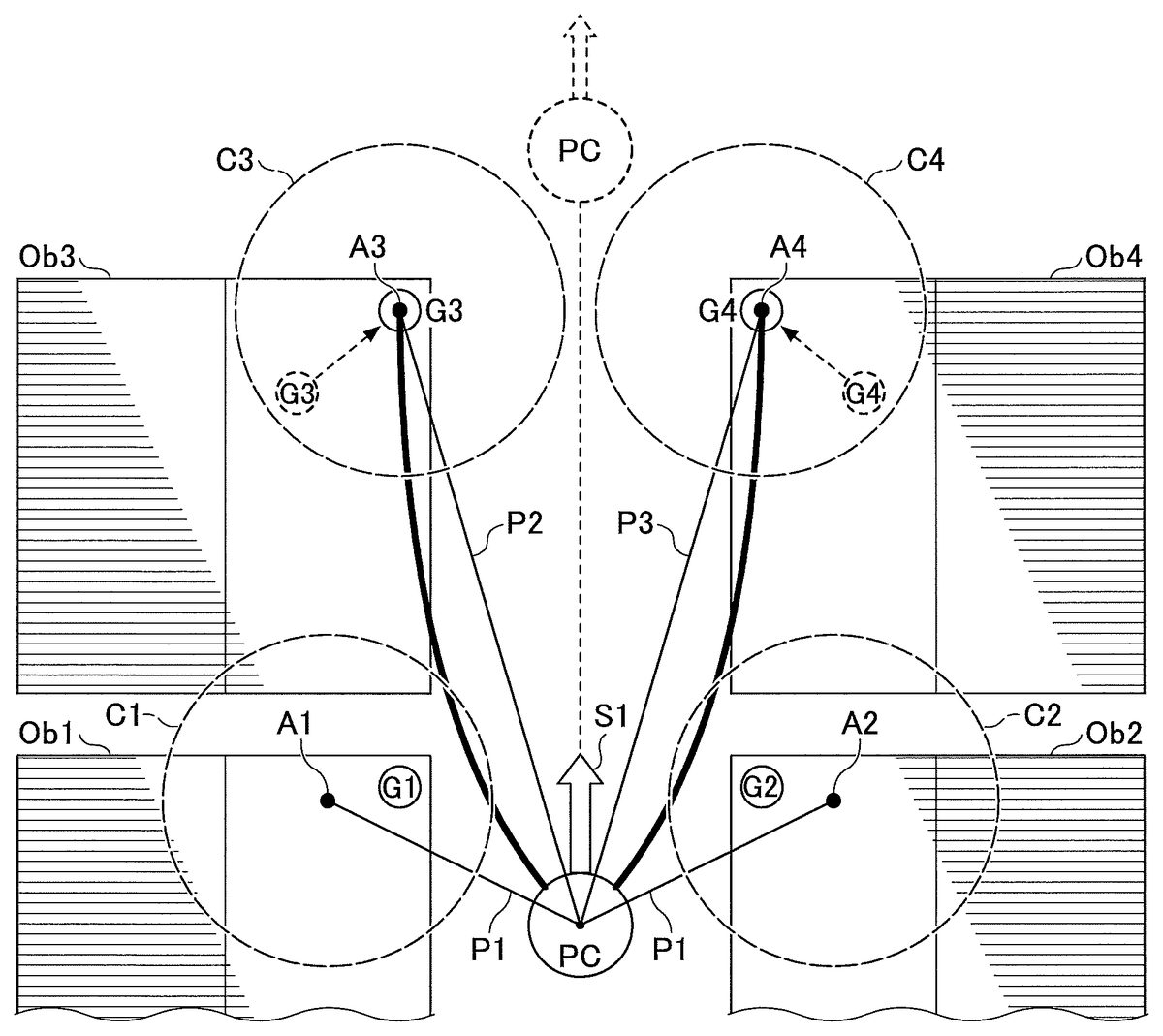
FIG. 6illustrates an example of a screen in which the player character PC is displayed. In the screen ofFIG. 6, the player character PC is moving along a road between objects (buildings) Ob1to Ob4at both sides toward a direction illustrated as “S1”. The screen ofFIG. 6illustrates a plan view of a background viewed from an upper direction in which ceiling portions of the four objects Ob1to Ob4and the player character PC are illustrated. Hereinafter, the objects Ob1to Ob4may be simply referred to as an object Ob as well.FIG. 6illustrates an example in which the moving direction S1of the player character PC, operated by a player, is to move from lower to upper of the drawing. At this time, the virtual bodies C1and C2whose centers A1and A2are positioned at left-hand and right-hand in front of the player character PC and apart from the center position of the player character PC for a distance P1, respectively, are placed. The distance P1may be a fixed value, or a variable value that is varied in accordance with the moving speed of the player character PC.
The virtual bodies C1and C2are an example of virtual bodies for detecting positions of edges of the objects Ob1and Ob2, respectively. The virtual bodies C1and C2are not actually displayed in the screen in the game. Although the virtual body is illustrated as sphere, the virtual body may have a different shape such as a capsule shape, a stick shape, a rectangular shape, a conical shape, a polygonal shape, an ellipse shape, a circular shape or the like. When the game provided by the data processing apparatus10of the embodiment is performed in a three dimensional virtual space, the virtual body is a three dimensional virtual object corresponding to the game. When the game provided by the data processing apparatus10of the embodiment is performed in a two dimensional virtual space, the virtual body is a two dimensional virtual object corresponding to the game.
Referring back toFIG. 5, next, the detection unit12determines a candidate target position of the virtual body in accordance with the moving speed and the operation direction of the player character PC (step S16). The detection unit12stores the determined candidate target position information in the candidate target position table31of the recording unit13. The number of the candidate target positions is not limited to four. For example, six candidate target positions G1to G6(G5and G6are positions illustrated by dot lines, respectively) are set as the candidate target positions for the next motion of the player character PC inFIG. 8.
The target position information may be determined based on at least one of the position, the moving speed and the operation direction of the player character PC.
Next, the detection unit12places virtual bodies C3and C4in front of the virtual bodies C1and C2with respect to the moving direction of the player character PC (step S18). The virtual bodies C3and C4are an example of virtual bodies for detecting positions of edges of the objects Ob3and Ob4, respectively. The virtual bodies C3and C4are not actually displayed in the screen in the game.
For example, the virtual bodies C3and C4whose centers A3and A4are at the positions of the objects Ob3and Ob4, that are positioned at left-hand and right-hand in front of the player character PC with respect to the moving direction S1of the player character PC, are placed inFIG. 6.
At this time, the virtual body C3is positioned such that its center position A3is apart from the center position of the player character PC for a distance P2. The virtual body C4is positioned such that its center position A4is apart from the center position of the player character PC for a distance P3. At this time, the relationship of the distances becomes P2>P1and P3>P1, however, P2=P3or P2≠P3.
The above relationship of the distances is satisfied when the player character PC moves in a forward direction while facing forward, in other words, when the direction of velocity is forward. On the other hand, for example, when the player character PC moves in a backward direction while facing forward, in other words, when the direction of velocity is backward, the relationship of the distances becomes P2<P1and P3P1and P5>P1, however, P4=P5or P4≠P5. With this, the coordinates of the four virtual bodies C1to C4in the virtual space are determined.
The above relationship of the distances is satisfied when the player character PC moves in a forward direction while facing forward, in other words, when the direction of velocity is forward. On the other hand, for example, when the player character PC moves in a backward direction while facing forward, in other words, when the direction of velocity is backward, the relationship of the distances becomes P4<P1and P5<P1.
For the examples illustrated inFIG. 6andFIG. 8, the operation directions S1and S2of the player character PC are the same. On the other hand, when the operation directions S1and S2of the player character PC are different, the virtual bodies C3and C4are placed at positions tilted from the moving direction of the player character PC in accordance with the operation directions S1and S2of the player character PC, respectively.
For example, when the operation direction of the player character PC is an obliquely right upward, the virtual bodies C3and C4are placed furthermore rightward than the virtual bodies C3and C4illustrated inFIG. 6andFIG. 8.
(Target Position Determining Process)
Next, an example of a target position determining process of the embodiment is described with reference toFIG. 9.FIG. 9is a flowchart illustrating an example of the target position determining process of the embodiment. The target position determining process of the embodiment is performed in accordance with the motion of the player character PC that targets the target position in the progression of the game.
When the process is started, the specifying unit14ray casts from the position of the player character PC toward the candidate target position stored in the candidate target position table31(step S40).
Next, the specifying unit14determines whether an object exists between the position of the player character PC and the candidate target position (step S42). When the specifying unit14determines that the object does not exist between the position of the player character PC and the candidate target position (NO of step S42), the process is finished.
On the other hand, when the specifying unit14determines that the object exists between the position of the player character PC and the candidate target position (YES of step S42), the specifying unit14recognizes the edge of the object as the candidate target position, and uses the newly recognized candidate target position as the target position of the edge of the object (step S44).
Here, it is assumed that the coordinate (xg3, yg3) of the candidate target position information312of the candidate target number311“G3” inFIG. 3is substituted by the coordinate (x14, y14) of the edge position information303of the virtual body number301“C3” inFIG. 2by the processes illustrated inFIG. 5andFIG. 9. Further, it is assumed that the coordinate (xg4, yg4) of the candidate target position information312of the candidate target number311“G4” inFIG. 3is substituted by the coordinate (x20, y20) of the edge position information303of the virtual body number301“C4” inFIG. 2by those processes.
As a result, for example, the candidate target position of the candidate target number “G3” is moved from the previously set position (illustrated by a dot line) to the edge position A3detected by causing the virtual body C3to be bounded inFIG. 6, and the candidate target position is optimized. Similarly, the candidate target position of the candidate target number “G4” is moved to the edge position A4detected by causing the virtual body C4to be bounded, and the candidate target position can be optimized. At this time, the candidate target positions of the candidate target numbers G1and G2, respectively, are not moved.
Similarly, for example, the candidate target position of the candidate target number “G5” (illustrated by a dot line) is moved to the edge position A3detected by the virtual body C3inFIG. 8. Similarly, the candidate target position of the candidate target number “G6” (illustrated by a dot line) is moved to the edge position A4detected by the virtual body C4. The candidate target positions of the candidate target numbers G1to G4, respectively, do not move. The candidate target positions G3and G4inFIG. 8may be omitted from targets for the process of comparing with the edge positions. Further, the candidate target positions G3and G4themselves may be omitted from the candidate target positions inFIG. 8.
Next, the motion control unit15controls the movement of the player character PC which targets the target position (step S46). Thereafter, the player character PC and the object are cooperatively moved (step S48), and the process is finished. As such, in this embodiment, the movement of the character can be controlled by cooperatively operating the character and the object that exists at the target position in accordance with a single input operation.
For example, the motion control unit15may control the movement of the player character PC such that laser light is emitted from a weapon possessed by the player character PC toward the target position in accordance with the input operation of the player. Further, the motion control unit15may control the movement of the player character PC such that the player character PC releases a bullet from a gun, releases a sword or an arrow, hits by a fist or the like, toward the target position.
Furthermore, for example, the motion control unit15may control the next movement of the player character PC, in accordance with the input operation of the player, such that a wire possessed by the player character PC is injected toward the target position and fixed at the target position.
For example, the motion control unit15may control the movement of the player character PC, in accordance with the input operation of the player, such that the player character PC is moved by a pendulum movement by two wires fixed at the two objects (target positions), respectively. The wires extending toward the target positions may be displayed as a linear line, or a wavy line having predetermined amplitude.
By the above processes, in this embodiment, the movement of the player character PC can be controlled by cooperatively operating the object Ob which exists between the player character PC and the target position by a single button operation by the player to the target position defined by the determined target position information.
For example, inFIG. 6andFIG. 8, wires, among weapons possessed by the player character PC, can be injected toward the candidate target positions G3and G4(toward the candidate target positions G5and G6inFIG. 8) to be fixed at the objects Ob when the player only performs a single button operation to use the weapon possessed by the player character PC. With this, by controlling the player character PC to perform a pendulum movement while being connected to the objects Ob3and Ob4(or G5and G6), a springy movement of the player character PC with a floating feeling can be displayed.
FIG. 10is a view illustrating another example of the edge detection and the target position. For the example illustrated inFIG. 10, the player performs a button operation to use a weapon possessed by the player character PC toward the objects Ob1to Ob6as targets. With this, a net or a bullet that is injected from the weapon possessed by the player character PC can hit the candidate target positions G1to G3. With this, it is possible to control the player character PC to perform a next movement while linking the player character PC with the objects Ob1to Ob3.
In this embodiment, the edge position can be detected by the virtual body whose position moves in accordance with the movement of the object Ob. With this, an optimal target position can be selected from the detected edge positions. In particular, in this embodiment, as illustrated inFIG. 10, an optimal target position can be selected from the detected edge positions for the moving object Ob. As a result, the movement of the player character PC while the player character PC is pulled toward the object Ob can be appropriately controlled.
InFIG. 5, the candidate target position is determined based on at least one of the position, the moving speed and the operation direction of the player character PC. As a result, inFIG. 6, the candidate target positions G3and G4are selected as the target positions in accordance with the operation direction S1and the moving speed of the player character PC. Further, inFIG. 8, the candidate target positions G5and G6are selected as the target positions in accordance with the operation direction S2and the moving speed of the player character PC. As another example, as illustrated inFIG. 11, the candidate target position G4may be selected as a target position in accordance with the operation direction S3and the moving speed of the player character PC. In such a case, the motion control unit15can display a springy movement of the player character PC with a floating feeling by controlling the player character PC to perform a pendulum movement by the wire fixed to the object Ob4.
As described above, according to the data processing apparatus10of the embodiment, collision between the virtual body C and the object Ob is generated by causing the virtual body C to be bounded. With this, edge positions of the object can be obtained in accordance with a motion status of the player character PC in real time during the game. The motion status of the player character PC may include the position of the player character PC, the operation direction of the player character PC and the moving speed of the player character PC in accordance with the input operation. The appropriate edge of the object is automatically detected during the game in accordance with at least one of them. Then, the player character in the virtual space can be appropriately moved based on the edge position as the target position. In particular, even when the object Ob dynamically moves, the player character PC can be appropriately operated in accordance with the position of the object Ob.
When the target position is determined, the virtual body C is moved to a next predetermined position for detecting a next edge position.
Further, there may be a case that a position appropriate for a target position does not exist in a background, for example, when the background is prairie or the like. In such a case, the candidate target position information312stored in the candidate target position table31ofFIG. 3are cleared. However, for a case that the background is changed from the prairie or the like to a background including a certain number of buildings or the like when the player character PC changes the moving direction for 180°, the specifying unit14sets coordinates of candidate target positions again, and stores the coordinates as the candidate target position312in the candidate target position table31ofFIG. 3. Then, the detection of the edge position of the embodiment is performed again.
According to the embodiment, it is possible to control a character to appropriately move in a virtual space.
Although a preferred embodiment of the data processing apparatus and the method of detecting position information has been specifically illustrated and described, it is to be understood that minor modifications may be made therein without departing from the spirit and scope of the invention as defined by the claims.
The present invention is not limited to the specifically disclosed embodiments, and numerous variations and modifications may be made without departing from the spirit and scope of the present invention.
For example, the edge position information of the object is selected from the plurality of contact position information at each of which the virtual body contacts the object at the upper portion of the object when the virtual body is bounded. However, alternatively, the edge position information of the object may be selected from a plurality of contact position information at which the virtual body contacts the object at a side portion or a bottom portion of the object when the virtual body is bounded. Further, the edge position information of the object may be selected from the contact position information at which the virtual body contacts the object and which is a characteristic portion of the object such as a projection portion, a corner portion, a concave portion or the like.
Further, the data processing apparatus10and the display29may be separately structured. For example, the data processing apparatus10may be connected to a TV device or the like, and a display of the TV device or the like may be used as the display29.
Claims
- A data processing apparatus comprising: a processor;and a memory storing instructions that, when executed, cause the processor to perform processes of displaying a character operated by an input operation of a player and a background in a virtual space on a screen, the background including an object, obtaining at least one of a position of the character, a moving speed of the character and an operation direction of the character in the virtual space based on the input operation, providing a virtual body for specifying characteristic position information regarding a shape of the object of the background in the virtual space based on the obtained at least one of the position of the character, the moving speed of the character and the operation direction of the character, the characteristic position information being an edge position of the object of the background, the virtual body not being displayed on the screen, the virtual body being provided such that the center of the virtual body is apart from the center position of the player by a predetermined distance, moving the virtual body to perform a predetermined motion to contact the object of the background and detecting contact position information at which the virtual body contacts the object of the background in the virtual space, and specifying characteristic position information regarding a shape of the object of the background based on the detected contact position information, the shape of the object of the background not being changed by the contact with the virtual body, wherein a size of the virtual body is determined based on a size of the object of the background.
- The data processing apparatus according to claim 1 , wherein the background includes a plurality of objects, wherein in the providing, a plurality of the virtual bodies are provided in the virtual space based on the obtained at least one of the position of the character, the moving speed of the character and the operation direction of the character, and wherein in the moving, each of the plurality of the virtual bodies is moved to perform the predetermined motion in the virtual space to detect the contact position information at which the plurality of the virtual bodies contact the plurality of the objects, respectively.
- The data processing apparatus according to claim 1 , wherein the instructions stored in the memory, when executed, cause the processor to further perform processes of setting the edge position of the object of the background as a target position of a next motion of the character based on the characteristic position information specified in the specifying, and controlling a motion of the character that targets the target position.
- The data processing apparatus according to claim 3 , wherein in the controlling, the motion of the character is controlled by a pendulum movement by targeting the target position.
- The data processing apparatus according to claim 4 , wherein in the controlling, the movement of the character is controlled by cooperatively operating the character and the object which exists at the target position in accordance with a single input operation to the determined target position.
- The data processing apparatus according to claim 1 , wherein the object of the background is not operated by an input operation of the player.
- The data processing apparatus according to claim 1 , wherein in the moving, the predetermined motion is to bound the virtual body to contact a plurality of positions of the object of the background, and wherein in the specifying, an edge position of the object of the background is specified based on the plurality of positions at each of which the virtual body contacts the object of the background.
- The data processing apparatus according to claim 1 , wherein the instructions stored in the memory, when executed, cause the processor to further perform processes of determining a candidate target position of a next motion of the character based on the obtained at least one of the position of the character, the moving speed of the character and the operation direction of the character, ray casting from the position of the character toward the candidate target position to determine whether the object of the background exists between the position of the character and the candidate target position, when it is determined that the object of the background exists between the position of the character and the candidate target position, setting the edge position of the object of the background as a new candidate target position of the next motion of the character, while when it is determined that the object of the background does not exist between the position of the character and the candidate target position, retaining the candidate target position, and selecting the candidate target position as a target position of the next motion of the character and controlling the movement of the character to target the target position.
- A method of detecting position information, performed by a computer, comprising: displaying a character operated by an input operation of a player and a background in a virtual space on a screen, the background including an object;obtaining at least one of a position of the character, a moving speed of the character and an operation direction of the character in the virtual space based on the input operation;providing a virtual body for specifying characteristic position information regarding a shape of the object of the background in the virtual space based on the obtained at least one of the position of the character, the moving speed of the character and the operation direction of the character, the characteristic position information being an edge position of the object of the background, the virtual body not being displayed on the screen, the virtual body being provided such that the center of the virtual body is apart from the center position of the player by a predetermined distance;moving the virtual body to perform a predetermined motion to contact the object of the background and detecting contact position information at which the virtual body contacts the object of the background in the virtual space;and specifying characteristic position information regarding a shape of the object of the background based on the detected contact position information, the shape of the object of the background not being changed by the contact with the virtual body, wherein a size of the virtual body is determined based on a size of the object of the background.
- The method of detecting position information according to claim 9 , wherein the object of the background is not operated by an input operation of the player.
- The method of detecting position information according to claim 9 , wherein in the moving, the predetermined motion is to bound the virtual body to contact a plurality of positions of the object of the background, and wherein in the specifying, an edge position of the object of the background is specified based on the plurality of positions at each of which the virtual body contacts the object of the background.
- The method of detecting position information according to claim 9 , further comprising: determining a candidate target position of a next motion of the character based on the obtained at least one of the position of the character, the moving speed of the character and the operation direction of the character;ray casting from the position of the character toward the candidate target position to determine whether the object of the background exists between the position of the character and the candidate target position;when it is determined that the object of the background exists between the position of the character and the candidate target position, setting the edge position of the object of the background as a new candidate target position of the next motion of the character, while when it is determined that the object of the background does not exist between the position of the character and the candidate target position, retaining the candidate target position;and selecting the candidate target position as a target position of the next motion of the character and controlling the movement of the character to target the target position.
- A non-transitory computer-readable recording medium having recorded thereon a program that causes a computer to execute a method of detecting position information, the method comprising: displaying a character operated by an input operation of a player and a background in a virtual space on a screen, the background including an object;obtaining at least one of a position of the character, a moving speed of the character and an operation direction of the character in the virtual space based on the input operation;providing a virtual body for specifying characteristic position information regarding a shape of the object of the background in the virtual space based on the obtained at least one of the position of the character, the moving speed of the character and the operation direction of the character, the characteristic position information being an edge position of the object of the background, the virtual body not being displayed on the screen, the virtual body being provided such that the center of the virtual body is apart from the center position of the player by a predetermined distance;moving the virtual body to perform a predetermined motion to contact the object of the background and detecting contact position information at which the virtual body contacts the object of the background in the virtual space;and specifying characteristic position information regarding a shape of the object of the background based on the detected contact position information, the shape of the object of the background not being changed by the contact with the virtual body, wherein a size of the virtual body is determined based on a size of the object of the background.
- The non-transitory computer-readable recording medium according to claim 13 , wherein the object of the background is not operated by an input operation of the player.
- The non-transitory computer-readable recording medium according to claim 13 , wherein in the moving, the predetermined motion is to bound the virtual body to contact a plurality of positions of the object of the background, and wherein in the specifying, an edge position of the object of the background is specified based on the plurality of positions at each of which the virtual body contacts the object of the background.
- The non-transitory computer-readable recording medium according to claim 13 , wherein the method of detecting position information further comprises determining a candidate target position of a next motion of the character based on the obtained at least one of the position of the character, the moving speed of the character and the operation direction of the character, ray casting from the position of the character toward the candidate target position to determine whether the object of the background exists between the position of the character and the candidate target position, when it is determined that the object of the background exists between the position of the character and the candidate target position, setting the edge position of the object of the background as a new candidate target position of the next motion of the character, while when it is determined that the object of the background does not exist between the position of the character and the candidate target position, retaining the candidate target position, and selecting the candidate target position as a target position of the next motion of the character and controlling the movement of the character to target the target position.
Disclaimer: Data collected from the USPTO and may be malformed, incomplete, and/or otherwise inaccurate.