U.S. Pat. No. 10,058,779
GAME APPARATUS, STORAGE MEDIUM HAVING GAME PROGRAM STORED THEREON, GAME SYSTEM, AND GAME PROCESSING METHOD
AssigneeNINTENDO CO., LTD.
Issue DateMay 5, 2017
Illustrative Figure
Abstract
When a first swing input is determined to have been made in a first movement start-possible state, in which a first object is allowed to start moving, and when the first object is put into the first movement start-possible state within a predetermined time period after the first swing input is determined to have been made, the first object is started to move in a virtual space based on at least the first swing input; and when a second swing input is determined to have been made in a second movement start-possible state, in which a second object is allowed to start moving, and when the second object is put into the second movement start-possible state within a predetermined time period after the second swing input is determined to have been made, the second object is started to move based on at least the second swing input.
Description
DETAILED DESCRIPTION OF NON-LIMITING EXAMPLE EMBODIMENTS A description is given below of a game apparatus, a game program, a game system, and a game processing method according to an exemplary embodiment. An information processing system1as an example of game system according to the exemplary embodiment includes a main body apparatus (information processing apparatus; acts as a game apparatus main body in the exemplary embodiment)2, a left controller3, and a right controller4. In another form, the information processing system may further include a cradle5(seeFIG. 6,FIG. 7, and the like) in addition to the above elements. In the information processing system1according to the exemplary embodiment, the left controller3and the right controller4are attachable to, and detachable from, the main body apparatus2. The information processing system1is usable as an integrated apparatus in a state where the left controller3and the right controller4are attached to the main body apparatus2. Alternatively, the main body apparatus2, the left controller3and the right controller4are usable as separate bodies (seeFIG. 2). The information processing system1is usable in a form in which an image is displayed on the main body apparatus2, and in a form in which an image is displayed on another display apparatus such as a TV or the like. In the former form, the information processing system1is usable as a mobile apparatus (e.g., a mobile game apparatus). In the latter form, the information processing system1is usable as a stationary apparatus (e.g., a stationary game apparatus). FIG. 1shows a state where the left controller3and the right controller4are attached to the main body apparatus2in an example of the information processing system1according to the exemplary embodiment. As shown inFIG. 1, the information processing system1includes the main body apparatus2, the left controller3, and the right controller4. The left controller3and the right controller4are attached to, and integrated with, the main body apparatus2. The main ...
DETAILED DESCRIPTION OF NON-LIMITING EXAMPLE EMBODIMENTS
A description is given below of a game apparatus, a game program, a game system, and a game processing method according to an exemplary embodiment. An information processing system1as an example of game system according to the exemplary embodiment includes a main body apparatus (information processing apparatus; acts as a game apparatus main body in the exemplary embodiment)2, a left controller3, and a right controller4. In another form, the information processing system may further include a cradle5(seeFIG. 6,FIG. 7, and the like) in addition to the above elements. In the information processing system1according to the exemplary embodiment, the left controller3and the right controller4are attachable to, and detachable from, the main body apparatus2. The information processing system1is usable as an integrated apparatus in a state where the left controller3and the right controller4are attached to the main body apparatus2. Alternatively, the main body apparatus2, the left controller3and the right controller4are usable as separate bodies (seeFIG. 2). The information processing system1is usable in a form in which an image is displayed on the main body apparatus2, and in a form in which an image is displayed on another display apparatus such as a TV or the like. In the former form, the information processing system1is usable as a mobile apparatus (e.g., a mobile game apparatus). In the latter form, the information processing system1is usable as a stationary apparatus (e.g., a stationary game apparatus).
FIG. 1shows a state where the left controller3and the right controller4are attached to the main body apparatus2in an example of the information processing system1according to the exemplary embodiment. As shown inFIG. 1, the information processing system1includes the main body apparatus2, the left controller3, and the right controller4. The left controller3and the right controller4are attached to, and integrated with, the main body apparatus2. The main body apparatus2is an apparatus that executes various processes (e.g., game process) in the information processing system1. The main body apparatus2includes a display12. The left controller3and the right controller4are each a device including an operation section allowing a user to make an input thereto.
FIG. 2shows an example of state where the left controller3and the right controller4are detached from the main body apparatus2. As shown inFIG. 1andFIG. 2, the left controller3and the right controller4are attachable to, and detachable from, the main body apparatus2. The left controller3is attachable to a left side surface (side surface on a positive side in an x-axis direction shown inFIG. 1) of the main body apparatus2, and is attachable to, and detachable from, the main body apparatus2by being slid along the left side surface of the main body apparatus2in a y-axis direction shown inFIG. 1. The right controller4is attachable to a right side surface (side surface on a negative side in the x-axis direction shown inFIG. 1) of the main body apparatus2, and is attachable to, and detachable from, the main body apparatus2by being slide along the right side surface of the main body apparatus2in the y-axis direction shown inFIG. 1. Hereinafter, the left controller3and the right controller4will occasionally be referred to collectively as “controllers”. In the exemplary embodiment, an “operation device” operable by a single user may be a single controller (e.g., one of the left controller3and the right controller4) or a plurality of controllers (e.g., both the left controller3and the right controller4, or at least either the left controller3or the right controller4and another controller). The “operation device” includes at least one controller. Hereinafter, an example of specific configuration of the main body apparatus2, the left controller3, and the right controller4will be described.
FIG. 3provides six orthogonal views showing an example of the main body apparatus2. As shown inFIG. 3, the main body apparatus2includes a generally plate-shaped housing11. In the exemplary embodiment, a main surface of the housing11(in other words, a front surface, i.e., a surface on which the display12is provided) has a roughly rectangular shape. In the exemplary embodiment, the housing11is longer in a left-right direction as described below. In the exemplary embodiment, a longer direction of the main surface of the housing11(i.e., x-axis direction shown inFIG. 1) will be referred to as a “width direction” (also referred to as the “left-right direction”), and a short direction of the main surface (i.e., y-axis direction shown inFIG. 1) will be referred to as a “length direction” (also referred to as an “up-down direction”). A direction perpendicular to the main surface (i.e., z-axis direction shown inFIG. 1) will be referred to as a “depth direction” (also referred to as a “front-rear direction”). The main body apparatus2is usable in an orientation in which the width direction extends in the horizontal direction. The main body apparatus2is also usable in an orientation in which the length direction extends in the horizontal direction. In this case, the housing11may be considered as being longer in the vertical direction.
The housing11may have any shape and size. For example, the housing11may have a mobile size. A single body of the main body apparatus2, or an integrated apparatus including the main body apparatus2and the left and right controllers3and4attached thereto, may act as a mobile apparatus. Alternatively, the main body apparatus2or the integrated apparatus may act as a handheld apparatus. Still alternatively, the main body apparatus2or the integrated apparatus may act as a portable apparatus.
As shown inFIG. 3, the main body apparatus2includes the display12provided on the main surface of the housing11. The display12displays an image (a still image or a moving image) acquired or generated by the main body apparatus2. In the exemplary embodiment, the display12is a liquid crystal display device (LCD). Alternatively, the display12may be a display apparatus of any type.
The main body apparatus2includes a touch panel13provided on a screen of the display12. In the exemplary embodiment, the touch panel13is of a type that allows a multi-touch input to be made (e.g., of an electrostatic capacitance type). Alternatively, the touch panel13may be of any type. For example, the touch panel13may be of a type that allows a single-touch input to be made (e.g., of a resistive type).
The main body apparatus2includes speakers (speakers88shown inFIG. 8) accommodated in the housing11. As shown inFIG. 3, the main surface of the housing11has speaker holes11aand11bformed therein. The speakers88output a sound through the speaker holes11aand11b.
As shown inFIG. 3, the main body apparatus2includes a left rail member15provided on the left side surface of the housing11. The left rail member15is provided to allow the left controller3to be detachably attached to the main body apparatus2. The left rail member15extends in the up-down direction on the left side surface of the housing11. The left rail member15is so shaped as to be engageable with a slider in the left controller3(slider40shown inFIG. 4), and a slide mechanism includes the left rail member15and the slider40. The slide mechanism allows the left controller3to be slidably and detachably attached to the main body apparatus2.
The main body apparatus2includes a left terminal17. The left terminal17allows the main body apparatus2to communicate with the left controller3in a wired manner The left terminal17is provided at a position where, in a case where the left controller3is attached to the main body apparatus2, the left terminal17comes into contact with a terminal in the left controller3(terminal42shown inFIG. 4). The specific position of the left terminal17is optional. In the exemplary embodiment, as shown inFIG. 3, the left terminal17is provided on a bottom surface of a groove in the left rail member15. In the exemplary embodiment, the left terminal17is provided near a lower end on the bottom surface of the groove of the left rail member15.
As shown inFIG. 3, components similar to the components provided on the left side surface of the housing11are provided on the right side of the housing11. Specifically, the main body apparatus2includes a right rail member19provided on the right side surface of the housing11. The right rail member19extends in the up-down direction on the right side surface of the housing11. The right rail member19is so shaped as to be engageable with a slider in the right controller4(slider62shown inFIG. 5), and a slide mechanism includes the right rail member19and the slider62. The slide mechanism allows the right controller4to be slidably and detachably attached to the main body apparatus2.
The main body apparatus2includes a right terminal21. The right terminal21is provided to allow the main body apparatus2to communicate with the right controller4in a wired manner. The right terminal21is provided at a position where, in a case where the right controller4is attached to the main body apparatus2, the right terminal21comes into contact with a terminal in the right controller4(terminal64shown inFIG. 5). The specific position of the right terminal21is optional. In the exemplary embodiment, as shown inFIG. 3, the right terminal21is provided on a bottom surface of a groove in the right rail member19. In the exemplary embodiment, the right terminal21is provided near a lower end of the bottom surface of the groove of the right rail member19.
As shown inFIG. 3, the main body apparatus2includes a first slot23. The first slot23is provided in an upper side surface of the housing11. The first slot23is so shaped as to allow a first type storage medium to be attached to the first slot23. The first type storage medium is, for example, a dedicated storage medium (e.g., dedicated memory card) for the information processing system1and an information processing apparatus of the same type as that of the information processing system1. The first type storage medium is used to, for example, store data usable by the main body apparatus2(e.g., saved data of an application or the like) and/or a program executable by the main body apparatus2(e.g., program for an application or the like). The main body apparatus2includes a power button28. As shown inFIG. 3, the power button28is provided on the upper side surface of the housing11. The power button28is provided to switch the power supply of the main body apparatus2between an on-state and an off-state.
The main body apparatus2includes a sound input/output terminal (specifically, earphone jack)25. That is, the main body apparatus2allows a microphone or an earphone to be attached to the sound input/output terminal25. As shown inFIG. 3, the sound input/output terminal25is provided on the upper side surface of the housing11.
The main body apparatus2includes sound volume buttons26aand26b.As shown inFIG. 3, the sound volume buttons26aand26bare provided on the upper side surface of the housing11. The sound volume buttons26aand26bare provided to give an instruction to adjust the volume of a sound output from the main body apparatus2. The sound volume button26ais provided to give an instruction to turn down the sound volume, and the sound volume button26bis provided to give an instruction to turn up the sound volume.
The housing11includes an exhaust hole11cformed thereon. As shown inFIG. 3, the exhaust hole11cis formed in the upper side surface of the housing11. The exhaust hole11cis formed to exhaust (in other words, release) heat generated inside the housing11to outside the housing11. That is, the exhaust hole11cmay be called a heat discharge hole.
The main body apparatus2includes a lower terminal27. The lower terminal27is provided to allow the main body apparatus2to communicate with the cradle5described below. As shown inFIG. 3, the lower terminal27is provided on a lower side surface of the housing11. In a case where the main body apparatus2is attached to the cradle5, the lower terminal27is connected to a terminal of the cradle5(main body terminal73shown inFIG. 7). In the exemplary embodiment, the lower terminal27is a USB connector (more specifically, a female connector).
The main body apparatus2includes a second slot24. In the exemplary embodiment, the second slot24is provided in the lower side surface of the housing11. In another exemplary embodiment, the second slot24may be provided in the same surface as the first slot23. The second slot24is so shaped as to allow a second type storage medium, different from the first type storage medium, to be attached to the second slot24. The second type storage medium may be, for example, a general-purpose storage medium. For example, the second type storage medium may be an SD card. Similarly to the first type storage medium, the second type storage medium is used to, for example, store data usable by the main body apparatus2(e.g., saved data of an application or the like) and/or a program executable by the main body apparatus2(e.g., program for an application or the like).
The housing11includes an absorption holes lldformed therein. As shown inFIG. 3, the air absorption holes11dare formed in the lower side surface of the housing11. The absorption holes11dare formed to absorb (in other words, introduce) air outside the housing11into the housing11. In the exemplary embodiment, the air absorption holes lldare formed in the surface opposite to the surface in which the exhaust hole11cis formed. Thus, heat in the housing11is released efficiently.
The shapes, the numbers, and the installation positions of the above-described components provided in the housing11(specifically, the buttons, the slots, the terminals, and the like) are optional. For example, in another exemplary embodiment, at least one of the power button28and the slots23and24may be provided on/in another side surface or a rear surface of the housing11. Alternatively, in another exemplary embodiment, the main body apparatus2may not include at least one of the above-described components.
FIG. 4provides six orthogonal views showing an example of the left controller3. As shown inFIG. 4, the left controller3includes a housing31. In the exemplary embodiment, the housing31is generally plate-shaped. A main surface of the housing31(in other words, a front surface. i.e., a surface on a negative side in the z-axis direction shown inFIG. 1) has a roughly rectangular shape. In the exemplary embodiment, the housing31is longer in the up-down direction inFIG. 1A(i.e., in the y-axis direction shown inFIG. 1). In a state of being detached from the main body apparatus2, the left controller3may be held in an orientation in which the longer side extends in the vertical direction. The housing31has such a shape and such a size as to be held by one hand, particularly, with the left hand when being held in an orientation in which the longer side extends in the vertical direction. The left controller3may also be held in an orientation in which the longer side extends in the horizontal direction. In a case of being held in an orientation in which the longer side extends in the horizontal direction of, the left controller3may be held with both of two hands of the user. The housing31has any shape. In another exemplary embodiment, the housing31may not be generally plate-shaped. The housing31may not be rectangular, and may be, for example, semicircular. The housing31may not be vertically long.
The length in the up-down direction of the housing31is approximately equal to the length in the up-down direction of the housing11of the main body apparatus2. The thickness of the housing31(i.e., length in the front-rear direction, in other words, the length in the z-axis direction shown inFIG. 1) is approximately equal to the thickness of the housing11of the main body apparatus2. Thus, in a case where the left controller3is attached to the main body apparatus2(seeFIG. 1), the user can hold the main body apparatus2and the left controller3with a feeling that he/she holds an integrated apparatus.
As shown inFIG. 4, the main surface of the housing31is shaped such that left corners thereof are more rounded than right corners thereof. Specifically, a connection portion between an upper side surface and a left side surface of the housing31and a connection portion between a lower side surface and the left side surface of the housing31are more rounded (in other words, are chamfered to have a greater roundness) than a connection portion between the upper side surface and a right side surface of the housing31and a connection portion between the lower side surface and the right side surface of the housing31. Thus, in a case where the left controller3is attached to the main body apparatus2(seeFIG. 1), the information processing system1as the integrated apparatus has a rounded shape on the left side. The information processing system1having such a shape is easy for the user to hold.
The left controller3includes an analog stick32. As shown inFIG. 4, the analog stick32is provided on the main surface of the housing31. The analog stick32is an example of direction input section usable to input a direction. The analog stick32includes a stick member that can be inclined in all directions parallel to the main surface of the housing31(i.e., 360° directions including up, down, left, right, and oblique directions). The user may incline the stick member to input a direction corresponding to a direction of the inclination (and to input a magnitude corresponding to an angle of the inclination). The direction input section may be a cross key, a slide stick, or the like. In the exemplary embodiment, the stick member may be pressed (in a direction perpendicular to the housing31) to make an input operation. That is, the analog stick32is an input section usable to input a direction and a magnitude corresponding to the direction of inclination and the amount of inclination of the stick member, and also usable to make a press input operation on the stick member.
The left controller3includes four operation buttons33through36(specifically, a right direction button33, a down direction button34, an up direction button35, and a left direction button36). As shown inFIG. 4, the four operation buttons33through36are provided below the analog stick32on the main surface of the housing31. In the exemplary embodiment, the four operation buttons are provided on the main surface of the left controller3. The number of operation buttons is optional. The operation buttons33through36are used to give instructions corresponding to various programs executable by the main body apparatus2(e.g., an OS program and an application program). In the exemplary embodiment, the operation buttons33through36are usable to input directions, and thus are termed the right direction button33, the down direction button34, the up direction button35, and the left direction button36. Alternatively, the operation buttons33through36may be used to give instructions other than directions.
The left controller3includes a “−” (minus) button47. As shown inFIG. 4, the “−” button47is provided on the main surface of the housing31, more specifically, is provided on an upper right area of the main surface. The “−” button47is used to give instructions corresponding to various programs executable by the main body apparatus2(e.g., an OS program and an application program). The “−” button47is used as, for example, a select button in a game application (e.g., as a button used to switch a selectable item).
In a case where the left controller3is attached to the main body apparatus2, the operation sections provided on the main surface of the left controller3(specifically, the analog stick32and the buttons33through36and47) are operated with, for example, the thumb of the left hand of the user holding the information processing system1as the integrated apparatus. In a case where the left controller3is used while being detached from the main body apparatus2and held in a horizontal orientation with both of two hands of the user, the above-described operation sections are operated with, for example, the thumbs of the left and right hands of the user holding the left controller3. Specifically, in this case, the analog stick32is operated with the thumb of the left hand of the user, and the operation buttons33through36are operated with the thumb of the right hand of the user.
The left controller3includes a first L-button38. The left controller3includes a ZL-button39. Similarly to the operation buttons33through36, the operation buttons38and39are used to give instructions corresponding to various programs executable by the main body apparatus2. As shown inFIG. 4, the first L-button38is provided on an upper left portion of the side surface of the housing31. The ZL-button39is provided on an upper left portion from the side surface to a rear surface of the housing31(more precisely, an upper left portion when the housing31is viewed from the front side thereof). That is, the ZL-button39is provided to the rear of the first L-button38(on a positive side in the z-axis direction shown inFIG. 1). In the exemplary embodiment, the upper left portion of the housing31has a rounded shape. Therefore, the first L-button38and the ZL-button39each have a rounded shape corresponding to the roundness of the upper left portion of the housing31. In a case where the left controller3is attached to the main body apparatus2, the first L-button38and the ZL-button39are located on an upper left portion of the information processing system1as the integrated apparatus.
The left controller3includes the slider40described above. As shown inFIG. 4, the slider40extends in the up-down direction on the right side surface of the housing31. The slider40is so shaped as to be engageable with the left rail member15of the main body apparatus2(more specifically, with the groove in the left rail member15). Thus, the slider40, when being engaged with the left rail member15, is secured so as not to be detached in a direction perpendicular to a slide direction (the slide direction is, in other words, the direction in which the left rail member15extends).
The left controller3includes the terminal42usable by the left controller3to communicate with the main body apparatus2in a wired manner The terminal42is provided at a position where, in a case where the left controller3is attached to the main body apparatus2, the terminal42comes into contact with the left terminal17(FIG. 3) of the main body apparatus2. The specific position of the terminal42is optional. In the exemplary embodiment, as shown inFIG. 4, the terminal42is provided on an attachment surface to which the slider40is attached. In the exemplary embodiment, the terminal42is provided near a lower end on the attachment surface of the slider40.
FIG. 5provides six orthogonal views showing an example of the right controller4. As shown inFIG. 5, the right controller4includes a housing51. In the exemplary embodiment, the housing51is generally plate-shaped. A main surface of the housing51(in other words, a front surface, i.e., a surface on the negative side in the z-axis direction shown inFIG. 1) has a roughly rectangular shape. In the exemplary embodiment, the housing51is longer in the up-down direction inFIG. 1A. In a state of being detached from the main body apparatus2, the right controller4may be held in an orientation in which the longer side extends in the vertical direction. The housing51has such a shape and such a size as to be held by one hand, particularly, with the right hand when being held in an orientation in which the longer side extends in the vertical direction. The right controller4may also be held in an orientation in which the longer side extends in the horizontal direction. In a case of being held in an orientation in which the longer side extends in the horizontal direction, the right controller4may be held with both of two hands of the user.
Similarly to the case of the housing31of the left controller3, the length in the up-down direction of the housing51of the right controller4is approximately equal to the length in the up-down direction of the housing11of the main body apparatus2, and the thickness of the housing51is approximately equal to the thickness of the housing11of the main body apparatus2. Thus, in a case where the right controller4is attached to the main body apparatus2(seeFIG. 1), the user can hold the main body apparatus2and the right controller4with a feeling that he/she holds an integrated apparatus.
As shown inFIG. 5, the main surface of the housing51is shaped such that right corners thereof are more rounded than left corners thereof. Specifically, a connection portion between an upper side surface and a right side surface of the housing51and a connection portion between a lower side surface and the right side surface of the housing51are more rounded (in other words, are chamfered to have a greater roundness) than a connection portion between the upper side surface and a left side surface of the housing51and a connection portion between the lower side surface and the left side surface of the housing51. Thus, in a case where the right controller4is attached to the main body apparatus2(seeFIG. 1), the information processing system1as the integrated apparatus has a rounded shape on the right side. The information processing system1having such a shape is easy for the user to hold.
Similarly to the left controller3, the right controller4includes an analog stick52as a direction input section. In the exemplary embodiment, the analog stick52has the same configuration as that of the analog stick32of the left controller3. Similarly to the left controller3, the right controller4includes four operation buttons53through56(specifically, an A-button53, a B-button54, an X-button55, and a Y-button56). In the exemplary embodiment, the four operation buttons53through56have the same mechanism as that of the four operation buttons33through36of the left controller3. As shown inFIG. 5, the analog stick52and the operation buttons53through56are provided on the main surface of the housing51. In the exemplary embodiment, the four operation buttons are provided on the main surface of the right controller4. The number of operation buttons is optional.
Now, in the exemplary embodiment, the positional relationship between the two types of operation sections (the analog stick and the operation buttons) of the right controller4is opposite to the positional relationship between the corresponding two types of operation sections of the left controller3. That is, in the right controller4, the analog stick52is located below the operation buttons53through56, whereas in the left controller3, the analog stick32is located above the operation buttons33through36. With such a positional arrangement, the left controller3and the right controller4are usable with similar operation feelings to each other when being detached from the main body apparatus2.
The right controller4includes a “+” (plus) button57. As shown inFIG. 5, the “+” button57is provided on the main surface of the housing51, more specifically, is provided on an upper left area of the main surface. Similarly to the other operation buttons53through56, the “+” button57is used to give instructions corresponding to various programs executable by the main body apparatus2(e.g., an OS program and an application program). The “+” button57is used as, for example, a start button in a game application (e.g., as a button used to give an instruction to start a game).
The right controller4includes a home button58. As shown inFIG. 5, the home button58is provided on the main surface of the housing51, more specifically, is provided on a lower left area of the main surface. The home button58is used to display a predetermined menu screen on the display12of the main body apparatus2. The menu screen, for example, allows an application, specified by the user from one or more applications executable by the main body apparatus2, to be started. The menu screen may be displayed, for example, when the main body apparatus2is started. In the exemplary embodiment, when the home button58is pressed in the state where an application is being executed by the main body apparatus2(i.e., in the state where an image of the application is displayed on the display12), a predetermined operation screen may be displayed on the display12(at this point, the menu screen may be displayed instead of the operation screen). The operation screen, for example, allows an instruction to finish the application and display the menu screen on the display12, an instruction to resume the application, or the like, to be given.
In a case where the right controller4is attached to the main body apparatus2, the operation sections (specifically, the analog stick52and the buttons53through58) provided on the main surface of the right controller4are operated with, for example, the thumb of the right hand of the user holding the information processing system1. In a case where the right controller4is used while being detached from the main body apparatus2and held in a horizontal orientation with both of two hands of the user, the above-described operation sections are operated with, for example, the thumbs of the left and right hands of the user holding the right controller4. Specifically, in this case, the analog stick52is operated with the thumb of the left hand of the user, and the operation buttons53through56are operated with the thumb of the right hand of the user.
The right controller4includes a first R-button60. The right controller4includes a ZR-button61. As shown inFIG. 5, the first R-button60is provided on an upper right portion of the side surface of the housing51. The ZR-button61is provided on an upper right portion from the side surface to a rear surface of the housing51(more precisely, an upper right portion when the housing51is viewed from the front side thereof). That is, the ZR-button61is provided to the rear of the first R-button60(on the positive side in the z-axis direction shown inFIG. 1). In the exemplary embodiment, the upper right portion of the housing51has a rounded shape. Therefore, the first R-button60and the ZR-button61each have a rounded shapes corresponding to the roundness of the upper right portion of the housing51. In a case where the right controller4is attached to the main body apparatus2, the first R-button60and the ZR-button61are located on an upper right portion of the information processing system1.
The left controller3includes a slider mechanism similar to that of the left controller3. That is, the right controller4includes the slider62described above. As shown inFIG. 5, the slider62extends in the up-down direction on the left side surface of the housing51. The slider62is so shaped as to be engageable with the right rail member19of the main body apparatus2(more specifically, with the groove in the right rail member19). Thus, the slider62, when being engaged with the right rail member19, is secured so as not to be detached in a direction perpendicular to the slide direction (the slide direction is, in other words, the direction in which the right rail member19extends).
The right controller4includes the terminal64usable by the right controller4to communicate with the main body apparatus2in a wired manner The terminal64is provided at a position where, in a case where the right controller4is attached to the main body apparatus2, the terminal64comes into contact with the right terminal21(FIG. 3) of the main body apparatus2. The specific position of the terminal64is optional. In the exemplary embodiment, as shown inFIG. 5, the terminal64is provided on an attachment surface to which the slider62is attached. In the exemplary embodiment, the terminal64is provided near a lower end on the attachment surface of the slider62.
Regarding the left controller3and the right controller4, the shapes, the numbers, and the installation positions of the above-described components provided in the housings31and51(specifically, the sliders, the sticks, the buttons, and the like) are optional. For example, in another exemplary embodiment, the left controller3and the right controller4may each include a direction input section of a type different from that of the analog stick. The slider40or62may be located at a position corresponding to the position of the rail member15or19provided in the main body apparatus2, for example, on the main surface or the rear surface of the housing31or51. In still another exemplary embodiment, the left controller3and the right controller4may not include at least one of the above-described components.
FIG. 6shows an overall configuration of another example of information processing system according to the exemplary embodiment. As shown inFIG. 6, for example, only the main body apparatus2, with the left controller3and the right controller4being detached therefrom, may be mounted on the cradle5. In another example, the integrated apparatus including the main body apparatus2and the left and right controllers3and4attached thereto may be mounted on the cradle5. The cradle5is communicable (via wired communication or wireless communication) with the stationary monitor6(e.g., stationary TV), which is an example of external display apparatus separate from the display12. As described below in detail, in a case where the integrated apparatus or a single body of the main body apparatus2is mounted on the cradle5, the information processing system1displays, on the stationary monitor6, an image acquired or generated by the main body apparatus2. In the exemplary embodiment, the cradle5has a function of charging the integrated apparatus or a single body of the main body apparatus2mounted thereon. The cradle5has a function of a hub apparatus (specifically, a USB hub).
FIG. 7shows an example of external configuration of the cradle5. The cradle5includes a housing on which the integrated apparatus or only the main body apparatus2is detachably mountable (or attachable). In the exemplary embodiment, as shown inFIG. 7, the housing includes a first supporting portion71including a groove71aformed therein, and a generally planar second supporting portion72.
As shown inFIG. 7, the groove71aformed in the first supporting portion71has a shape corresponding to the shape of a lower portion of the above-described integrated apparatus. Specifically, the groove71ais so shaped as to allow the lower portion of the integrated apparatus to be inserted thereto. More specifically, the shape of the groove71ais generally matched to the shape of the lower portion of the main body apparatus2. Therefore, the lower portion of the integrated apparatus may be inserted into the groove71a,so that the integrated apparatus is mounted on the cradle5. The second supporting portion72supports a front surface of the integrated apparatus having the lower portion inserted into the groove71a(i.e., supports the surface on which the display12is provided). The second supporting portion72allows the cradle5to support the integrated apparatus more stably. The shape of the housing shown inFIG. 7is merely illustrative. In another exemplary embodiment, the housing of the cradle5may have any shape that allows the main body apparatus2to be mounted thereon.
As shown inFIG. 7, the cradle5includes the main body terminal73usable by the cradle5to communicate with the integrated apparatus. As shown inFIG. 7, the main body terminal73is provided on a bottom surface of the groove71a,which is formed in the first supporting portion71. More specifically, the main body terminal73is provided at a position where, in a case where the integrated apparatus is attached to the cradle5, the lower terminal27of the main body apparatus2comes into contact with the main body terminal73. In the exemplary embodiment, the main body terminal73is a USB connector (more specifically, a male connector). In the exemplary embodiment, the integrated apparatus is attachable to the cradle5in any of two orientations in the depth direction, namely, regardless of whether the front surface of the integrated apparatus faces the second support portion72or a rear surface of the integrated apparatus faces the second support portion72. The lower terminal27of the main body apparatus2and the main body terminal73of the cradle5have symmetrical shapes in the depth direction (i.e., the z-axis direction shown inFIG. 1), and thus the main body apparatus2and the cradle5are communicable with each other in whichever orientation, among the above-mentioned two orientations in the depth direction, the integrated apparatus may be mounted on the cradle5.
Although not shown inFIG. 7, the cradle5includes a terminal on a rear surface of the housing (in the exemplary embodiment, includes a plurality of terminals, specifically, a monitor terminal132, a power supply terminal134, and extension terminals137shown inFIG. 10). The details of these terminals will be described below.
Regarding the cradle5, the shapes, the numbers, and the installation positions of the above-described components (specifically, the housing, the terminals, the buttons, and the like) are optional. For example, in another exemplary embodiment, the housing may have another shape with which the integrated apparatus including the main body apparatus2and the left and right controllers3and4attached thereto, or a single body of the main body apparatus2, is supported. Some of the terminals provided in the housing may be provided on a front surface of the housing. In still another exemplary embodiment, the cradle5may not include at least one of the above-described components.
FIG. 8is a block diagram showing an example of internal configuration of the main body apparatus2. The main body apparatus2includes components81through98shown inFIG. 8in addition to the components shown inFIG. 3. At least one of the components81through98may be mounted as an electronic component on an electronic circuit board and accommodated in the housing11.
The main body apparatus2includes a CPU (Central Processing Unit)81. The CPU81is an information processing section that executes various types of information process executable by the main body apparatus2. The CPU81executes an information processing program (e.g., game program) stored on a storage section (specifically, an internal storage medium such as a flash memory84or the like, an external storage medium attached to each of the slots23and24, or the like) to execute various types of information process.
The main body apparatus2includes the flash memory84and the DRAM (Dynamic Random Access Memory)85as examples of internal storage medium built in the main body apparatus2. The flash memory84and the DRAM85are connected with the CPU81. The flash memory84is mainly usable to store various pieces of data (or programs) to be saved on the main body apparatus2. The DRAM85is usable to temporarily store various pieces of data used for the information process.
The main body apparatus2includes a first slot interface (hereinafter, the “interface” will be abbreviated as “I/F”)91. The main body apparatus2includes a second slot I/F92. The first slot I/F91and the second slot I/F92are connected with the CPU81. The first slot I/F91is connected with the first slot23, and follows an instruction from the CPU81to read and write data from and to the first type storage medium (e.g., SD card) attached to the first slot23. The second slot I/F92is connected with the second slot24, and follows an instruction from the CPU81to read and write data from and to the second type storage medium (e.g., dedicated memory card) attached to the second slot24.
The CPU81appropriately transfers data between the flash memory84/the DRAM85and the above-described storage mediums to execute the above-described information process.
The main body apparatus2includes a network communication section82. The network communication section82is connected with the CPU81. The network communication section82communicates (specifically, via wireless communication) with an external apparatus via a network. In the exemplary embodiment, in a first communication form, the network communication section82is connected with a wireless LAN by a system compliant with the Wi-Fi standards to communicate with an external apparatus. In a second communication form, the network communication section82wirelessly communicates with another main body apparatus2of the same type by a predetermined communication system (e.g., communication based on an original protocol or infrared light communication). The wireless communication in the second communication form may be performed with another main body apparatus2located in a closed local network area and thus realizes a so-called “local communication”, in which a plurality of the main body apparatuses2are communicated directly to each other to transmit and receive data.
The main body apparatus2includes a controller communication section83. The controller communication section83is connected with the CPU81. The controller communication section83wirelessly communicates with the left controller3and/or the right controller4. The communication system between the main body apparatus2and the left controller3or the right controller4is optional. In the exemplary embodiment, the controller communication section83performs communication compliant with the Bluetooth (registered trademark) standards with the left controller3and with the right controller4.
The CPU81is connected with the left terminal17, the right terminal21, and the lower terminal27. When communicating with the left controller3in a wired manner, the CPU81transmits data to the left controller3via the left terminal17and also receives operation data from the left controller3via the left terminal17. When communicating with the right controller4in a wired manner, the CPU81transmits data to the right controller4via the right terminal21and also receives operation data from the right controller4via the right terminal21. When communicating with the cradle5, the CPU81transmits data to the cradle5via the lower terminal27. As described above, in the exemplary embodiment, the main body apparatus2can perform both wired communication and wireless communication with each of the left controller3and the right controller4. In a case where the integrated apparatus including the main body apparatus2and the left and right controllers3and4attached thereto, or a single body of the main body apparatus2, is attached to the cradle5, the main body apparatus2outputs data (e.g., image data or sound data) to the stationary monitor6via the cradle5.
The main body apparatus2can communicate with a plurality of the left controllers3simultaneously (in other words, in parallel). The main body apparatus2can communicate with a plurality of the right controllers4simultaneously (in other words, in parallel). Thus, the user can input data to the main body apparatus2using the plurality of left controllers3and the plurality of right controllers4.
The main body apparatus2includes a touch panel controller86, which is a circuit that controls the touch panel13. The touch panel controller86is connected between the touch panel13and the CPU81. Based on a signal from the touch panel13, the touch panel controller86generates data indicating, for example, the position where a touch input has been provided. Then, the touch panel controller86outputs the data to the CPU81.
The display12is connected with the CPU81. The CPU81displays, on the display12, an generated image (e.g., image generated by executing the above-described information process) and/or an externally acquired image.
The main body apparatus2includes a codec circuit87and the speakers (specifically, a left speaker and a right speaker)88. The codec circuit87is connected with the speakers88and the sound input/output terminal25and also connected with the CPU81. The codec circuit87controls the input and output of sound data to and from the speakers88and the sound input/output terminal25. Specifically, when receiving sound data from the CPU81, the codec circuit87performs D/A conversion on the sound data and outputs a resultant sound signal to the speakers88or the sound input/output terminal25. As a result, a sound is output from the speakers88or a sound output section (e.g., earphone) connected with the sound input/output terminal25. When receiving a sound signal from the sound input/output terminal25, the codec circuit87performs A/D conversion on the sound signal and outputs resultant sound data in a predetermined format to the CPU81. The sound volume buttons26are connected with the CPU81. Based on an input to the sound volume buttons26, the CPU81controls the volume of the sound to be output from the speakers88or the sound output section.
The main body apparatus2includes a power control section97and a battery98. The power control section97is connected with the battery98and the CPU81. Although not shown inFIG. 8, the power control section97is connected with various components of the main body apparatus2(specifically, components that receive power supplied from the battery98, the left terminal17, and the right terminal21). Based on a command from the CPU81, the power control section97controls the supply of power from the battery98to the above-mentioned components. The power control section97is connected with the power button28. Based on an input to the power button28, the power control section97controls the supply of power to the above-mentioned components. Specifically, in a case where an operation of turning off the power supply is performed on the power button28, the power control section97stops the supply of power to all or a part of the above-mentioned components. In a case where an operation of turning on the power supply is performed on the power button28, the power control section97starts the supply of power to all or a part of the above-mentioned components. The power control section97outputs, to the CPU81, information indicating an input to the power button28(specifically, information indicating whether or not the power button28has been pressed).
The battery98is connected with the lower terminal27. In a case where an external charging apparatus (e.g., cradle5) is connected with the lower terminal27and power is supplied to the main body apparatus2via the lower terminal27, the battery98is charged with the supplied power.
The main body apparatus2includes a cooling fan96usable to release heat inside the main body apparatus2. The cooling fan96is operated to introduce air outside the housing11through the absorption holes11dand also to release air inside the housing11through the exhaust hole11c,so that heat inside the housing11is released. The cooling fan96is connected with the CPU81, and the operation of the cooling fan96is controlled by the CPU81. The main body apparatus2includes a temperature sensor95, which detects the temperature inside the main body apparatus2. The temperature sensor95is connected with the CPU81, and a detection result provided by the temperature sensor95is output to the CPU81. Based on the detection result provided by the temperature sensor95, the CPU81controls the operation of the cooling fan96.
FIG. 9is a block diagram showing an example of internal configuration of the information processing system1. Among the components of the information processing system1, the components of the main body apparatus2are shown in detail inFIG. 8and thus are omitted inFIG. 9.
The left controller3includes a communication control section101, which communicates with the main body apparatus2. As shown inFIG. 9, the communication control section101is connected with components including the terminal42. In the exemplary embodiment, the communication control section101can communicate with the main body apparatus2by wired communication via the terminal42and also by wireless communication with no use of the terminal42. The communication control section101controls a method of communication performed by the left controller3with the main body apparatus2. In in a case where the left controller3is attached to the main body apparatus2, the communication control section101communicates with the main body apparatus2via the terminal42. In a case where the left controller3is detached from the main body apparatus2, the communication control section101wirelessly communicates with the main body apparatus2(specifically, the controller communication section83). The wireless communication between the controller communication section83and the communication control section101is performed in conformity to, for example, the Bluetooth (registered trademark) standards.
The left controller3includes a memory102such as, for example, a flash memory or the like. The communication control section101includes, for example, a microcomputer (or a microprocessor) and executes firmware stored on the memory102to perform various types of process.
The left controller3includes buttons103(specifically, the buttons33through39,43and44). The left controller3includes the analog stick (“stick” inFIG. 9)32. The buttons103and the analog stick32each output information regarding an operation performed thereon to the communication control section101repeatedly at appropriate timing.
The left controller3includes an acceleration sensor104. In the exemplary embodiment, the acceleration sensor104detects magnitudes of linear accelerations in predetermined three axis directions (e.g., X-, Y- and Z-axis directions shown inFIG. 11). The acceleration sensor104may detect an acceleration in one axis direction or accelerations in two axis directions. The left controller3includes an angular velocity sensor105. In the exemplary embodiment, the angular velocity sensor105detects angular velocities about predetermined three axes (e.g., X, Y and Z axes shown inFIG. 11). The angular velocity sensor105may detect an angular velocity about one axis or angular velocities about two axes. The acceleration sensor104and the angular velocity sensor105are connected with the communication control section101. Detection results provided by the acceleration sensor104and the angular velocity sensor105are each output to the communication control section101repeatedly at appropriate timing.
The communication control section101acquires information regarding an input (specifically, information regarding an operation or a detection result provided by any of the sensors) from each of the input sections (specifically, the buttons103, the analog stick32, and the sensors104and105). The communication control section101transmits, to the main body apparatus2, operation data including the acquired information (or information obtained by performing a predetermined process on the acquired information). The operation data is transmitted repeatedly at a rate of once every predetermined time period. The interval at which information regarding an input is transmitted to the main body apparatus2may or may not be the same among the input sections.
The above-mentioned operation data is transmitted to the main body apparatus2, so that the main body apparatus2obtains the inputs provided to the left controller3. That is, the main body apparatus2distinguishes operations made on the buttons103and the analog stick32from each other, based on the operation data. The main body apparatus2computes information regarding the motion and/or the attitude of the left controller3based on the operation data (specifically, the detection results provided by the acceleration sensor104and the angular velocity sensor105).
The left controller3includes a vibrator107usable to give notification to the user by a vibration. In the exemplary embodiment, the vibrator107is controlled by a command from the main body apparatus2. Specifically, upon receipt of the above-mentioned command from the main body apparatus2, the communication control section101drives the vibrator107in accordance with the command The left controller3includes an amplifier106. Upon receipt of the above-mentioned command, the communication control section101outputs a control signal corresponding to the command to the amplifier106. The amplifier106amplifies the control signal from the communication control section101, generates a driving signal for driving the vibrator107, and outputs the driving signal to the vibrator107. As a result, the vibrator107is operated.
The left controller3includes a power supply section108. In the exemplary embodiment, the power supply section108includes a battery and a power control circuit. Although not shown inFIG. 9, the power control circuit is connected with the battery and also connected with components of the left controller3(specifically, components that receive power supplied from the battery). The power control circuit controls the supply of power from the battery to the above-mentioned components. The battery is connected with the terminal42. In the exemplary embodiment, in a case where the left controller3is attached to the main body apparatus2, the battery is charged via the terminal42with power supplied from the main body apparatus2under a predetermined condition.
As shown inFIG. 9, the right controller4includes a communication control section111, which communicates with the main body apparatus2. The right controller4includes a memory112, which is connected with the communication control section111. The communication control section111is connected with components including the terminal64. The communication control section111and the memory112have functions similar to those of the communication control section101and the memory102, respectively, of the left controller3. Thus, the communication control section111can communicate with the main body apparatus2by wired communication via the terminal64and also by wireless communication with no use of the terminal64(specifically, communication compliant with the Bluetooth (registered trademark) standards). The communication control section111controls a method of communication performed by the right controller4with the main body apparatus2.
The right controller4includes input sections similar to the input sections of the left controller3(specifically, buttons113, the analog stick52, an acceleration sensor114, and an angular velocity sensor115). These input sections have functions similar to those of the input sections of the left controller3and operate similarly to the input sections of the left controller3.
The right controller4includes a vibrator117and an amplifier116. The vibrator117and the amplifier116operate similarly to the vibrator107and the amplifier106, respectively, of the left controller3. Specifically, the communication control section111, in accordance with a command from the main body apparatus2, uses the amplifier116to cause the vibrator117to operate.
The right controller4includes a power supply section118. The power supply section118has a function similar to that of the power supply section108of the left controller3, and operates similarly to the power supply section108. That is, the power supply section118controls the supply of power to components that receive power supplied from a battery. In a case where the right controller4is attached to the main body apparatus2, the battery is charged via the terminal64with power supplied from the main body apparatus2under a predetermined condition.
The right controller4includes a processing section121. The processing section121is connected with the communication control section111and is also connected with an NFC communication section122. The processing section121, in accordance with a command from the main body apparatus2, performs a process of managing the NFC communication section122. For example, the processing section121controls an operation of the NFC communication section122in accordance with a command from the main body apparatus2. The processing section121controls the start of the NFC communication section122or controls an operation of the NFC communication section122(specifically, reading, writing, or the like) performed on a communication partner thereof (e.g., NFC tag). The processing section121receives, from the main body apparatus2via the communication control section111, information to be transmitted to the communication partner and passes the information to the NFC communication section122. The processing section121also acquires, via the NFC communication section122, information received from the communication partner and transmits the information to the main body apparatus2via the communication control section111. In accordance with a command from the main body apparatus2, the processing section121performs a process of managing an infrared image capturing section123. For example, the processing section121causes the infrared image capturing section123to perform an image capturing operation, or acquires information based on an image capturing result (information of a captured image, information computed from such information, or the like) and transmits the information to the main body apparatus2via the communication control section111.
FIG. 10is a block diagram showing an example of internal configuration of the cradle5. The internal configuration of the main body apparatus2is shown in detail inFIG. 8and thus is omitted inFIG. 10.
As shown inFIG. 10, the cradle5includes a conversion section131and a monitor terminal132. The conversion section131is connected with the main body terminal73and the monitor terminal132. The conversion section131converts formats of signals of an image (or video) and a sound received from the main body apparatus2into formats in which the image and the sound are to be output to the stationary monitor6. In the exemplary embodiment, the main body apparatus2outputs an image signal and a sound signal as display port signals (i.e., signals compliant with the DisplayPort standard) to the cradle5. In the exemplary embodiment, the communication between the cradle5and the stationary monitor6is performed based on the HDMI (registered trademark) standard. That is, the monitor terminal132is an HDMI terminal, and the cradle5and the stationary monitor6are connected to each other by an HDMI cable. The conversion section131converts display port signals (specifically, signals representing the video and the sound) received from the main body apparatus2via the main body terminal73into HDMI signals. The HDMI signals obtained as a result of the conversion are output to the stationary monitor6via the monitor terminal132.
The cradle5includes a power control section133and a power supply terminal134. The power supply terminal134is connectable with a charging apparatus (e.g., an AC adapter or the like; not shown). In the exemplary embodiment, the power supply terminal134is connected with an AC adapter, and mains electricity is supplied to the cradle5. In a case where the main body apparatus2is attached to the cradle5, the power control section133supplies power from the power supply terminal134to the main body apparatus2via the main body terminal73. As a result, the battery98of the main body apparatus2is charged.
The cradle5includes a connection processing section136and extension terminals137. The extension terminals137are each connectable with another apparatus. In the exemplary embodiment, the cradle5includes a plurality of (more specifically, three) USB terminals as the extension terminals137. The connection processing section136is connected with the main body terminal73and the extension terminals137. The connection processing section136has a function of a USB hub and, for example, manages the communication between an apparatus connected with any of the extension terminals137and the main body apparatus2connected with the main body terminal73(i.e., transmits a signal from a certain apparatus to other apparatuses while distributing the signal appropriately). As described above, in the exemplary embodiment, the information processing system1is communicable with another apparatus via the cradle5. The connection processing section136may be capable to change the communication speed, or supply power to an apparatus connected to any of the extension terminals137.
As described above, in the information processing system1according to the exemplary embodiment, the left controller3and the right controller4are attachable to, and detachable from, the main body apparatus2. The integrated apparatus including the main body apparatus2and the left and right controllers3and4attached thereto, or a single body of the main body apparatus2, may be attached to the cradle5to output an image (and a sound) to the stationary monitor6. Hereinafter, an operation of the information processing system1will be described in which the main body apparatus2, in a state where the left controller3and the right controller4are detached therefrom, is attached to the cradle5to output an image (or a sound) to the stationary monitor6.
As described above, in the exemplary embodiment, the information processing system1is usable in the state where the left controller3and the right controller4are detached from the main body apparatus2(referred to as a “separate state”). The information processing system1in the separate state is usable to make an operation on the same application (e.g., a game application) in a case where a single user uses both of the left controller3and the right controller4. In a case where a plurality of users make an operation on the same application, a plurality of pairs of the left controller3and the right controller4may be prepared, so that each of the users uses one of such pairs.
FIG. 11andFIG. 12show an example in which a single user uses the information processing system1in the separate state while holding a pair of the left controller3and the right controller4. As shown inFIG. 11andFIG. 12, in the separate state, the user can view an image displayed on the stationary monitor6while holding the left controller3with his/her left hand and holding the right controller4with his/her right hand to make an operation.
For example, in the exemplary embodiment, the user holds the left controller3, which is longer in the up-down direction inFIG. 1Aand is generally plate-shaped, with his/her left hand such that the left controller3is oriented as follows: a downward direction in the longer direction (the negative y-axis direction shown inFIG. 1) is downward in the vertical direction, the side surface facing the main body apparatus2when the left controller3is attached to the main body apparatus2(side surface on which the slider40is provided) is directed forward, (direction away from the user), and the main surface (surface on which the analog stick32and the like are provided) is directed rightward. The user holds the right controller4, which is longer in the up-down direction inFIG. 1Aand is generally plate-shaped, with his/her right hand such that the right controller4is directed as follows: a downward direction in the longer direction (the negative y-axis direction shown inFIG. 1) is downward in the vertical direction, the side surface facing the main body apparatus2when the right controller4is attached to the main body apparatus2(side surface on which the slider62is provided) is directed forward, and the main surface (surface on which the analog stick52and the like are provided) is directed leftward. From the state of holding the left controller3with his/her left hand and holding the right controller4with his/her right hand (hereinafter, the attitude of each of the left controller3and the right controller4in the above-described orientation may be referred to as a “reference attitude”), the user moves each of the controllers3and4upward, downward, leftward, rightward, forward or rearward, rotates each of the controllers3and4, or swings each of the controllers3and4. Thus, a game is played in accordance with the motion or the attitude of each of the controllers3and4.
For easier understanding of the direction of acceleration or angular velocity caused in the left controller3, the following directions will be defined for the left controller3.
The forward direction in the above-described held state (direction from the rounded side surface toward the side surface attachable to the main body apparatus2; the negative x-axis direction shown inFIG. 1) will be referred to as a “positive X-axis direction”. The rightward direction in the above-described held state (direction from the rear surface toward the main surface; the negative z-axis direction shown inFIG. 1) will be referred to as a “positive Y-axis direction”. The upward direction in the above-described held state (upward direction in the longer direction; the positive y-axis direction shown inFIG. 1) will be referred to as a “positive Z-axis direction”. The acceleration sensor104of the left controller3is capable of detecting an acceleration in each of the X-, Y- and Z-axis directions. The angular velocity sensor105is capable of detecting an angular velocity about each of the X-, Y- and Z-axis directions. For easier understanding of the direction of acceleration or angular velocity caused in the right controller4, the following directions will be defined for the right controller4. The forward direction in the above-described held state (direction from the rounded side surface toward the side surface attachable to the main body apparatus2; the positive x-axis direction shown inFIG. 1) will be referred to as a “positive X-axis direction”. The rightward direction in the above-described held state (direction from the main surface toward the rear surface; the positive z-axis direction shown inFIG. 1) will be referred to as a “positive Y-axis direction”. The upward direction in the above-described held state (upward direction in the longer direction; the positive y-axis direction shown inFIG. 1) will be referred to as a “positive Z-axis direction”. The acceleration sensor114of the right controller4is capable of detecting an acceleration in each of the X-, Y- and Z-axis directions. The angular velocity sensor115is capable of detecting an angular velocity about each of the X-, Y- and Z-axis directions.
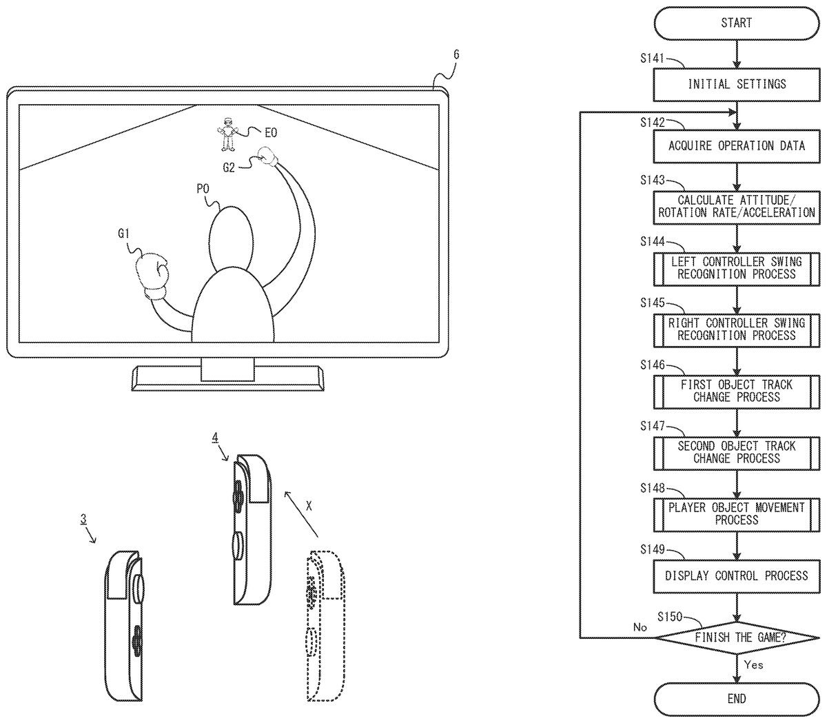
FIG. 13throughFIG. 15each show an example of game image displayed in a game played by the left controller3and the right controller4being moved. As shown inFIG. 13, in this game example, an image of a game in which a player object PO and an opponent object EO fight against each other (e.g., boxing game) is displayed on the stationary monitor6. The user operating the left controller3and the right controller4may swing the left controller3and/or the right controller4or change the attitude of the left controller3and/or the right controller4to operate the player object PO. For example, the user may swing the left controller3to control the motion of a first object G1, which represents the left glove (left fist) of the player object PO, and may swing the right controller4to control the motion of a second object G2, which represents the right glove (right fist) of the player object PO. Specifically, in a case where the user makes an operation of swinging his/her left hand holding the left controller3as if throwing a left punch, the first object G1representing the left glove of the player object PO moves toward a position where the opponent object EO is located. In a case where the user makes an operation of swinging his/her right hand holding the right controller4as if throwing a right punch, the second object G2representing the right glove of the player object PO moves toward the position where the opponent object EO is located.
For example, as shown inFIG. 14, in a case where the right controller4is swung as if being protruded forward (in the positive X-axis direction of the right controller4) from a state shown inFIG. 13where neither the left controller3nor the right controller4is moved, the second object G2of the player object PO moves toward the opponent object EO in accordance with the movement of the right controller4. As a result, a game image showing that the player object PO throws a right punch to the opponent object EO is displayed.
The direction of the movement of the first object G1is set by the attitude of the left controller3when the left controller3is swung as if being protruded. The direction of the movement of the second object G2is set by the attitude of the right controller4when the right controller4is swung as if being protruded. In a case where, for example, the right controller4is moved in the positive X-axis direction as shown inFIG. 14, the movement direction of the second object G2is set in accordance with the attitude in the roll direction of the right controller4at the time of the movement. For example, in exemplary embodiment, an inclination of the Y-axis direction of the right controller4with respect to the direction in which the gravitational acceleration acts in a real space while the right controller4is moving is calculated, and the movement direction of the second object G2is calculated based on the resultant inclination of the Y-axis direction. Specifically, in a case where the inclination of the Y-axis direction indicates that the right controller4is rotated rightward in the roll direction with respect to the reference attitude, the second object G2moves rightward in a virtual space. In a case where the inclination of the Y-axis direction indicates that the right controller4is rotated leftward in the roll direction with respect to the reference attitude, the second object G2moves leftward in the virtual space. The angle at which the movement direction is shifted in the rightward direction or the leftward direction is calculated in accordance with the angle of inclination of the Y-axis direction.
In this game example, even in a case where the distance between the player object PO and the opponent object EO is relatively long in the virtual space, a punch may be thrown. One of the arms of the player object PO is extended, so that the first object G1or the second object G2move a relatively long distance. The first object G1or the second object G2finishes moving after colliding against another object (e.g., opponent object EO) or after moving a predetermined distance, and returns to a movement start position, from which the first object G1or the second object G2started moving (e.g., the position of the left hand or the right hand of the player object PO shown inFIG. 13). The first object G1or the second object G2returns to the movement start position, and thus a next movement toward the opponent object EO is permitted to be made. In other words, the next punch is permitted to be thrown. Therefore, a time period from the start of the movement of the first object G1or the second object G2from the movement start position until the return thereof to the movement start position is longer than such a time period of a general boxing game.
In this game example, such a movement time period may be utilized to change a track of the movement in accordance with the attitude or the motion of the left controller3or the right controller4even while the first object G1or the second object G2is moving (typically, while the first object G1or the second object G2is moving toward the opponent object EO). For example, in a case where the left controller3or the right controller4is rotated in the roll direction or in the yaw direction from the attitude thereof at the time of start of the movement of the first object G1or the second object G2, the track of the first object G1or the second object G2is changed in accordance with the rotation.
In an example, in the exemplary embodiment, the rotation rate (angular velocity) of the left controller3or the right controller4about the X axis after the first object G1or the second object G2starts moving is set as the rotation rate in the roll direction. The track of the first object G1or the second object G2is changed based on the rotation rate about the X axis while the first object G1or the second object G2is moving. Specifically, in a case where the rotation rate at which the left controller3is rotated about the X axis rightward in the roll direction while the first object G1is moving is obtained, the track of the first object G1is changed rightward in the virtual space. In a case where the rotation rate at which the left controller3is rotated about the X axis leftward in the roll direction while the first object G1is moving is obtained, the track of the first object G1is changed leftward in the virtual space. In a case where the rotation rate at which the right controller4is rotated about the X axis rightward in the roll direction while the second object G2is moving is obtained, the track of the second object G2is changed rightward in the virtual space. In a case where the rotation rate at which the right controller4is rotated about the X axis leftward in the roll direction while the second object G2is moving is obtained the track of the second object G2is changed leftward in the virtual space.
In another example, in the exemplary embodiment, the rotation rate (angular velocity) of the left controller3or the right controller4about the gravity direction in the real space after the first object G1or the second object G2starts moving is set as the rotation rate in the yaw direction. The track of the first object G1or the second object G2is changed based on the rotation rate about the gravity direction while the first object G1or the second object G2is moving. Specifically, in a case where the rotation rate at which the left controller3is rotated about the gravity direction rightward in the yaw direction while the first object G1is moving is obtained, the track of the first object G1is changed rightward in the virtual space. In a case where the rotation rate at which the left controller3is rotated about the gravity direction leftward in the yaw direction while the first object G1is moving is obtained, the track of the first object G1is changed leftward in the virtual space. In a case where the rotation rate at which the right controller4is rotated about the gravity direction rightward in the yaw direction while the second object G2is moving is obtained, the track of the second object G2is changed rightward in the virtual space. In a case where the rotation rate at which the right controller4is rotated about the gravity direction leftward in the yaw direction while the second object G2is moving is obtained, the track of the second object G2is changed leftward in the virtual space.
In this game example, a determination on whether or not the left controller3or the right controller4has been swung is made based on the magnitude of the acceleration caused in the left controller3or the right controller4. When the left controller3is determined to have been swung in the positive X-axis direction in a state where the first object G1is located at the movement start position (hereinafter, this state will be referred to as a “first movement start-possible state”), the first object G1starts moving from the movement start position toward the opponent object EO. When the right controller4is determined to have been swung in the positive X-axis direction in a state where the second object G2is located at the movement start position (hereinafter, this state will be referred to as a “second movement start-possible state”), the second object G2starts moving from the movement start position toward the opponent object EO. In the exemplary embodiment, even when the first object G1is not in the first movement start-possible state, as long as the first object G1is put into the first movement start-possible state within a predetermined time period after the left controller3is determined to have been swung in the positive X-axis direction, the movement of the first object G1may be started from the movement start position toward the opponent object EO in accordance with the swing operation made on the left controller3. Even when the second object G2is not in the second movement start-possible state, as long as the second object G2is put into the second movement start-possible state within a predetermined time period after the right controller4is determined to have been swung in the positive X-axis direction, the movement of the second object G2may be started from the movement start position toward the opponent object EO in accordance with the swing operation made on the right controller4. As described above, in the exemplary embodiment, even when the first object G1and/or the second object G2is not in the first movement start-possible state and/or the second movement start-possible state, the left controller3and/or the right controller4may be swung to issue an instruction to start moving the first object G1and/or the second object G2. Therefore, even in a game in which a state where an operation instruction is issuable is caused intermittently, an operation is allowed to be made easily. Namely, as described above, in this game example, the time period from the start of the movement of the first object G1or the second object G2from the movement start position until the return thereof to the movement start position is longer than such a time period of a general boxing game. Therefore, it is conceivable that an operation of swinging the left controller3or the right controller4is made before the first object G1or the second object G2is put into the first movement start-possible start state or the second movement start-possible start state. Even when such an operation is made, such an operation is not invalidated but may be utilized for the game operation.
In this game example, as shown inFIG. 15, the first object G1and the second object G2may start moving at the same time from the movement start position to perform a predetermined action. For example, in a case where one of the first object G1and the second object G2starts moving and the other of the first object G1and the second object G2starts moving within a predetermine time period after the start of the one object, a “both-hand punch action”, by which the first object G1and the second object G2act as a pair, is started. The “both-hand punch action” is as follows. It is displayed in the game image that a collision region A is formed between the first object G1and the second object G2while the first object G1and the second object G2are moving in the virtual space, and the first object G1and the second object G2move toward the opponent object EO in a state where the collision region A is formed. When the first object G1, the second object G2or the collision region A, while moving, collides against the opponent object EO, a predetermined action is made on the opponent object EO that causes heavier damage thereon than when only the first object G1or only the second object G2collides against the opponent object EO. In an example, the “both-hand punch action” may provide an action of flinging the opponent object EO at the time of the collision or an action of making the opponent object EO unable to move. Even during the execution of the “both-hand punch action”, the track of the movement of the first object G1and/or the second object G2may be changed in accordance with the attitude or the motion of the left controller3and/or the right controller4. The track of the movement of the first object G1and/or the second object G2may be changed, so that the range of the collision region A is changed. Therefore, a strategic attack may be made to the opponent object EO.
In this game example, the player object PO may be moved in the virtual space in accordance with the motion or the attitude of both of the left controller3and the right controller4. For example, when the both of the left controller3and the right controller4are rotated in the pitch direction or in the roll direction in the real space, the player object PO may be moved in accordance with the post-rotation inclination thereof. This will be described specifically. The inclination angles of the X-axis direction and the Y-axis direction of the left controller3with respect to the gravity direction in the real space, and the inclination angles of the X-axis direction and the Y-axis direction of the right controller4with respect to the gravity direction in the real space, are calculated. When the both of the left controller3and the right controller4are determined, based on the resultant inclination angles, to be inclined forward, the player object PO is moved forward in the virtual space by the movement amount in accordance with the forward inclination angles of both of the left controller3and the right controller4(e.g., the average value of the inclination angles of the left controller3and the right controller4). When the both of the left controller3and the right controller4are determined, based on the resultant inclination angles, to be inclined rearward, the player object PO is moved rearward in the virtual space by the movement amount in accordance with the rearward inclination angles of both of the left controller3and the right controller4(e.g., the average value of the inclination angles of the left controller3and the right controller4). When the both of the left controller3and the right controller4are determined, based on the resultant inclination angles, to be inclined leftward, the player object PO is moved leftward in the virtual space by the movement amount in accordance with the leftward inclination angles of both of the left controller3and the right controller4(e.g., the average value of the inclination angles of the left controller3and the right controller4). When the both of the left controller3and the right controller4are determined, based on the resultant inclination angles, to be inclined rightward, the player object PO is moved rightward in the virtual space by the movement amount in accordance with the rightward inclination angles of both of the left controller3and the right controller4(e.g., the average value of the inclination angles of the left controller3and the right controller4).
Shown with reference toFIG. 13throughFIG. 15is an example of game played by one user with the stationary monitor6(for example, the opponent object EO is automatically controlled by the CPU81). The game may be played by a plurality of users. In a case where the game is played by, for example, two users, the users each hold a pair of the left controller3and the right controller4, and the users operate different player objects from each other. A display region of the stationary monitor6is divided into two regions, and an image for each of the users (image, as seen from the player object operated by each user, of the player object operated by the other player) is displayed in each of the divided regions. The users each make an operation of throwing a punch to the player object operated by the other user in such an operation environment, so that the player object of one of the users fights against the player object operated by the other user.
In a case where a plurality of users play a game, the information processing system1may communicate with another apparatus (e.g., another information processing system1) to transmit and receive game data necessary to play the game. In such a case, the information processing apparatus may transmit and receive data with another apparatus connected with the Internet (wide area network) via the network communication section82described above, or may transmit and receive data by use of a so-called “local communication”, by which communication is directly made with another apparatus located in a closed local network area.
Now, with reference toFIG. 16throughFIG. 23, an example of process executed by the information processing system1in the exemplary embodiment will be described.FIG. 16shows an example of data area set in the DRAM85of the main body apparatus2in the exemplary embodiment. In the DRAM85, data used in another process is stored in addition to the data shown inFIG. 16. Such data used in another process will not be described in detail.
In a program storage area of the DRAM85, various programs Pa executable by the information processing system1is stored. In the exemplary embodiment, the various programs Pa include a communication program usable for wireless communication with the left controller3or the right controller4described above, an application program usable to perform an information process (e.g., game process) based on data acquired from the left controller3and/or the right controller4, a program usable to switch display devices on which images are to be displayed in accordance with the attachment or detachment of the main body apparatus2to or from the cradle5, and the like. The various programs Pa may be stored on the flash memory84in advance, may be acquired from a storage medium attachable to, or detachable from, the information processing system1(e.g., the first type storage medium attached to the first slot23or the second type storage medium attached to the second slot24) and stored on the DRAM85, or may be acquired from another apparatus via a network such as the Internet or the like and stored on the DRAM85. The CPU81executes the various programs Pa stored on the DRAM85.
In a data storage area of the DRAM85, various types of data usable for a communication process, an information process or the like executable by the information processing system1are stored. In the exemplary embodiment, operation data Da, attitude data Db, angular velocity data Dc, acceleration data Dd, threshold value data De, curve value data Df, rotation rate data Dg, swing flag data Dh, movement flag data Di, action flag data Dj, return flag data Dk, movement start-possible flag data Dl, player object position data Dm, collision region data Dn, opponent object position data Do, image data Dp and the like are stored.
The operation data Da is operation data appropriately acquired from the left controller3and the right controller4. As described above, the operation data transmitted from each of the left controller3and the right controller4includes information regarding inputs from the input sections (specifically, the buttons, the analog sticks, and the sensors) (the information regarding the inputs specifically include information on the operations and detection results provided by the sensors). In the exemplary embodiment, the operation data is transmitted from the left controller3and the right controller4at a predetermined cycle via wireless communication, and the operation data Da is appropriately updated using the received operation data. The operation data Da may be updated every frame, which is a cycle of the process executed by the information processing system1as described below, or may be updated every cycle by which the operation data is transmitted via the above-described wireless communication.
The attitude data Db represents an attitude of each of the left controller3and the right controller4with respect to the direction of the gravitational acceleration in the real space. For example, the attitude data Db includes, for example, data representing the direction of the gravitational acceleration acting on each of the left controller3and the right controller4, data representing the X-, Y- and Z-axis directions with respect to the gravitational acceleration direction.
The angular velocity data Dc represents an angular velocity caused in each of the left controller3and the right controller4. For example, the angular velocity data Dc includes data representing the angular velocity about the X, Y- and Z axes caused in each of the left controller3and the right controller4.
The acceleration data Dd represents an acceleration caused in each of the left controller3and the right controller4. For example, the acceleration data Dd includes data representing the acceleration caused in each of the left controller3and the right controller4in each of the X-, Y- and Z-axis directions excluding the gravitational acceleration.
The threshold value data De represents a threshold value usable to make a determination on a swing motion made on each of the left controller3and the right controller4. The curve value data Df represents a curve value C usable to calculate the movement direction or the track of each of the first object G1and the second object G2. The rotation rate data Dg represents a motion of each of the left controller3and the right controller4(rotation rate V of each of the left controller3and the right controller4) while the first object G1or the second object G2is moving.
The swing flag data Dh represents a swing flag, which is set to ON when the left controller3and the right controller4are each determined to have been swung. The movement flag Di represents a movement flag, which is set to ON when the first object G1and the second object G2are each moving in the virtual space. The action flag data Dj represents an action flag, which is set to ON when an action is being performed by use of the first object G1and the second object G2as a pair. The return flag data Dk represents a return flag, which is set to ON when the first object G1and the second object G2are each moving in a return path toward the movement start position in the virtual space. The movement start-possible flag data Dl represents a movement start-possible flag, which is set to ON when the first object G1is put into the first movement start-possible state or the second object G2is put into the second movement start-possible state.
The player object position data Dm represents the position and the direction (movement direction) of each of the first object G1, the second object G2, and the player object PO in the virtual space. The collision region data Dn represents the position, the shape, and the range of the collision region A in the virtual space. The opponent object position data Do represents the position and the orientation of the opponent object EO in the virtual space or represents the position and the orientation of an object released from the opponent object EO (e.g., object representing the left glove (left fist) or the right glove (right fist)) in the virtual space.
The image data Dp is usable to display an image (e.g., an image of a virtual object, an image of the field, or an image of the background) on the display screen of the display12of the main body apparatus2or the stationary monitor6during the game.
Now, an example of information process (game process) in the exemplary embodiment will be described in detail.FIG. 17is a flowchart showing an example of game process executed by the information processing system1.FIG. 18andFIG. 19provides a flowchart showing, in detail, a sub routine of a controller swing recognition process executed in step S144and step S145shown inFIG. 17.FIG. 20throughFIG. 22provide a flowchart showing, in detail, a sub routine of an object track change process executed in step S146and step S147shown inFIG. 17.FIG. 23is a flowchart showing, in detail, a sub routine of a player object movement process executed in step S148shown inFIG. 17. In the exemplary embodiment, the series of processes shown inFIG. 17throughFIG. 23is executed by the CPU81executing a communication program and a predetermined application program (game program) included in the various programs Pa. The timing to start the game process shown inFIG. 17throughFIG. 23is optional.
The process in each of the steps shown inFIG. 17throughFIG. 23is merely illustrative, and the order of the processes executed in the steps may be changed as long as substantially the same result is obtained. Another process may be executed in addition to (or instead of) the processes executed in the steps. In the exemplary embodiment, the process in each of the steps will be described as being executed by the CPU81. A part of the processes in the steps may be executed by a processor other than the CPU81or a dedicated circuit. A part of the processes executed by the main body apparatus2may be executed by another information processing apparatus communicable with the main body apparatus2(e.g., server communicable with the main body apparatus2via a network). Namely, the processes shown inFIG. 17throughFIG. 23may be executed by cooperation of a plurality of information processing apparatuses including the main body apparatus2.
Referring toFIG. 17, the CPU81performs initial settings for the game process (step S141) and advances the game process to the next step. For example, in the initial settings, the CPU81initializes parameters usable to perform the processes described below. Also in the initial settings, the CPU81sets a game field in which the game is played, and sets initial positions of the player object OP and the opponent object EO on the game field to update the player object position data Dm and the opponent object position data Do. The CPU81also sets the movement directions of the first object G1and the second object G2to default values (e.g., forward direction) as the initial values to update the player object position data Dm. The CPU81sets the movement start-possible flag represented by the movement start-possible flag data Dl to ON.
Next, the CPU81acquires the operation data from the left controller3and the right controller4to update the operation data Da (step S142), and advances the game process to the next step.
Next, the CPU81calculates the attitude, the angular velocity, and the acceleration of each of the left controller3and the right controller4(step S143), and advances the game process to the next step. For example, the CPU81acquires, from the operation data Da, data representing the acceleration caused in each of the left controller3and the right controller4, calculates the direction of the gravitational acceleration acting on each of the left controller3and the right controller4, and updates the attitude data Db by use of the data representing the direction. The gravitational acceleration may be extracted by any method. For example, an acceleration component caused, on average, to each of the left controller3and the right controller4may be calculated and extracted as the gravitational acceleration. The CPU81calculates, as the attitude of the left controller3, the X-, Y- and Z-axis directions of the left controller3with respect to the direction of the gravitational acceleration calculated regarding the left controller3, and updates the attitude data Db by use of the data representing the attitude. The CPU81calculates, as the attitude of the right controller4, the X-, Y- and Z-axis directions of the right controller4with respect to the direction of the gravitational acceleration calculated regarding the right controller4, and updates the attitude data Db by use of the data representing the attitude. The CPU81acquires, from the operation data Da, data representing the angular velocity caused in each of the left controller3and the right controller4, calculates the angular velocity of each of the left controller3and the right controller4about each of the X, Y and Z axes, and updates the angular velocity data Dc by use of the data representing the angular velocity. The CPU81acquires, from the operation data Da, data representing the acceleration caused in each of the left controller3and the right controller4, deletes the above-mentioned gravitational acceleration component from the acceleration caused in each of the left controller3and the right controller4in the X-, Y- and Z-axis directions, and updates the acceleration data Dd by use of the data representing the post-deletion acceleration.
After the X-, Y- and Z-axis directions with respect to the gravitational acceleration are calculated, the attitude of each of the left controller3and the right controller4may be updated only in accordance with the angular velocity about each of the X, Y and Z axes. Alternatively, in order to prevent a situation where the relationship between the attitude of each of the left controller3and the right controller4and the gravitational acceleration direction is shifted as a result of errors being accumulated, the X-, Y- and Z-axis directions with respect to the gravitational acceleration direction may be calculated at each predetermined cycle to correct the attitude of each of the left controller3and the right controller4.
Next, the CPU81executes a left controller swing recognition process (step S144), and advances the game process to step S145. Hereinafter, with reference toFIG. 18andFIG. 19, the left controller swing recognition process executed in step S144will be described.
Referring toFIG. 18, the CPU81sets the swing flag that is set for the process on the left controller3to OFF to update the swing flag data Dh (step S161), and advances the game process to the next step.
Next, the CPU81determines whether or not to skip a swing determination on the left controller3(step S162). For example, when the left controller3is in a swung-back state, the CPU81skips the swing determination. When the swing determination on the left controller3is to be skipped, the CPU81advances the game process to step S163. By contrast, when the swing determination on the left controller3is to be made, the CPU81advances the game process to step S164.
In a first example of method by which the left controller3is determined to be in the swung-back state, the CPU81refers to the attitude data Db to acquire the angular velocity of the left controller3about the Y axis. When the left controller3is rotated toward the user (e.g., when the left controller3is rotated such that the positive Z-axis direction is directed toward the user), the CPU81provides a positive determination result in step S162. In a second example of method by which the left controller3is determined to be in the swung-back state, the CPU81refers to the attitude data Db to acquire the attitude of the left controller3. When the left controller3is inclined rearward with respect to the gravitational acceleration direction (e.g., when the positive X-axis direction of the left controller3is upward with respect to the horizontal direction in the real space), the CPU81provides a positive determination result in step S162. In a third example of method by which the left controller3is determined to be in the swung-back state, the CPU81refers to the acceleration data Dd to acquire the acceleration caused in the left controller3. When the left controller3is moving toward the player (e.g., when the acceleration caused in the left controller3includes a negative X-axis direction component of the left controller3), the CPU81provides a positive determination result in step S162.
In step S163, when the magnitude of the acceleration caused in the left controller3at the current point is larger than a threshold value usable to make the swing determination on the left controller3, the CPU81sets, as the threshold value, the magnitude of the acceleration caused in the left controller3at the current point to update the threshold value data De, and advances the game process to step S164. As is made clear below, in the exemplary embodiment, when the magnitude of the acceleration caused in the left controller3excluding a Y-axis direction component (hereinafter, such a magnitude of the acceleration will be referred to as an “XZ acceleration”) exceeds the threshold value, the left controller3is determined to have been swung. In step S163, when the magnitude of the acceleration caused in the left controller3at the current point (i.e., the magnitude of the acceleration caused in the left controller3at the current point excluding the Y-axis direction component) is larger than the threshold value, the magnitude of the acceleration is set as the threshold value usable for the swing determination. As a result, the CPU81determines not to skip the swing determination in step S162. Namely, step S163is executed when the left controller3is in the swung-back state. Thus, when the left controller3is swung back after an operation of throwing a punch, the left controller3is prevented from being incorrectly determined to have been swung so as to throw a punch.
In step S164, the CPU81determines whether or not the magnitude of the XZ acceleration caused in the left controller3is larger than the threshold value. When the magnitude of the XZ acceleration caused in the left controller3is larger than the threshold value, the CPU81advances the game process to step S165. By contrast, when the magnitude of the XZ acceleration caused in the left controller3is less than, or equal to, the threshold value, the CPU81advances the game process to step S168. In the exemplary embodiment, in order to determine whether or not the left controller3is swung so as to throw a punch, namely, whether or not the left controller3is swung so as to move in the positive X-axis direction, the magnitude of the acceleration caused in the left controller3excluding the Y-axis direction component is compared against a predetermined value (threshold value set in step S163described above or in step S167or S168described below). Therefore, in step S164, the CPU81refers to the acceleration data Dd to acquire the acceleration caused in each of the X-axis direction and the Z-axis direction of the left controller3and calculates the magnitude of the XZ acceleration caused in the left controller3by use of the acquired accelerations. When the left controller3is not in the swung-back state, if the magnitude of the XZ acceleration exceeds the predetermined value or a threshold value based on the predetermined value, the CPU81determines that the left controller3has been swung so as to throw a punch.
In step S165, the CPU81determines whether or not a temporary variant B is 0. When the temporary variant B is 0, the CPU81advances the game process to step S166. By contrast, when the temporary variant B is not 0, the CPU81advances the game process to step S167.
In step S166, the CPU81sets the swing flag that is set for the process on the left controller3to ON to update the swing flag data Dh, sets a predetermined frame number as the temporary variant B, and advances the game process to step S167. As can be seen, the swing flag set for the process on the left controller3is set to ON when the left controller3is determined to have been swung so as to throw a punch and the temporary variant B is 0.
In step S166, the “predetermined frame number” set as the temporary variant B is temporarily set as a time period in which, immediately after the left controller3is determined to have been swung so as to throw a punch, the next swing determination is skipped (time period in which the swing flag is not permitted to be set to ON). In the exemplary embodiment, the “predetermined frame number” is set to, for example, 12 frames. For example, even after the left controller3is determined to have been swung, the acceleration caused in the left controller3may be kept increased. In such a case, the swing determination in step S164keeps on providing a positive determination result. If all such positive determination results are regarded as indicating that the left controller3has been swung so as to throw a punch, the determination on the punch cannot be made as being intended. Therefore, in the exemplary embodiment, the swing determination is skipped for a predetermined time period (e.g., 12 frames) after the left controller3is determined to have been swung so as to throw a punch. In another embodiment, a time period, in which the acceleration caused in the left controller3is kept increasing (specifically, time period in which the XZ acceleration is kept increasing) after the left controller3is determined to have been swung so as to throw a punch and the swing flag is set to ON, may be set as a time period in which the swing flag is not permitted to be set to ON again.
In step S167, the CPU81sets the magnitude of the acceleration caused in the left controller3at the current point as the threshold value usable to make a swing determination on the left controller3to update the threshold value data De, and advances the game process to step S169.
When, in step S164, the magnitude of the XZ acceleration caused in the left controller3is determined to be less than, or equal to, the threshold value, the CPU81makes the threshold value, usable to make a swing determination on the left controller3, close to a predetermined value to update the threshold value data De, and advances the game process to step S169. In an example, the CPU81makes the threshold value represented by the threshold value data De closer to the predetermined value by a predetermined amount to set a new threshold value, and updates the threshold value data De by use of the new threshold value. In another example, the CPU81makes the threshold value represented by the threshold value data De closer to the predetermined value by a predetermined ratio to set a new threshold value, and updates the threshold value data De by use of the new threshold value. As can be seen, in a case where the threshold value usable to make a swing determination on the left controller3is made closer to the predetermined value, even if the threshold value is increased by execution of the processes in step S163or step S167, the swing determination on the left controller3is permitted to be made by use of the intended predetermined value when a predetermined time period lapses.
In step S169, the CPU81determines whether or not the temporary variant B is larger than 0. When the temporary variant B is larger than 0, the CPU81advances the game process to step S170. By contrast, when the temporary variant B is 0, the CPU81advances the game process to step S171(seeFIG. 19).
In step S170, the CPU81subtracts1from the temporary variant B to set a new temporary variant B, and advances the game process to step S171(seeFIG. 19).
Referring toFIG. 19, in step S171, the CPU81refers to the swing flag data Dh to determine whether or not the swing flag set for the process on the left controller3is set to ON. When the swing flag set for the process on the left controller3is set to ON, the CPU81advances the game process to step S172. By contrast, when the swing flag set for the process on the left controller3is set to OFF, the CPU81advances the game process to step S173.
In step S172, the CPU81sets a predetermined frame number as a temporary variant S usable to count the number of frames processed after the left controller3is determined to have been swung so as to throw a punch, and advances the game process to step S175. In a case where the first object G1is put into the first movement start-possible state within a predetermined time period after the left controller3is determined to have been swung so as to throw a punch, a process to start moving the first object G1is executed. The predetermined frame number set as the temporary variant S is a parameter corresponding to the predetermined time period. In the exemplary embodiment, the temporary variant S is set to 15 frames, for example. Thus, even in a case where the first object G1is not in the first movement start-possible state, when the first object G1is put into the first movement start-possible state within 15 frames after the left controller3is determined to have been swung so as to throw a punch, a process to start moving the first object G1is executed.
When, in step S171, determining that the swing flag is set to OFF, the CPU81determines whether or not the temporary variant S is larger than 0. When the temporary variant S is larger than 0, the CPU81advances the game process to step S174. By contrast, when temporary variant S is 0, the CPU81advances the game process to step S175.
In step S174, the CPU81subtracts 1 from the temporary variant S to set a new temporary variant S, and advances the game process to step S175.
In step S175, the CPU81determines whether or not the temporary variant S is larger than 0. When the temporary variant S is larger than 0, the CPU81advances the game process to step S176. By contrast, when temporary variant S is 0, the CPU81finishes the process in this sub routine.
In step S176, the CPU81refers to the movement start-possible flag data D1to determine whether or not the movement start-possible flag set for the process on the first object G1is set to ON. When the movement start-possible flag set for the process on the first object G1is set to ON, the CPU advances the game process to step S177. By contrast, when the movement start-possible flag set for the process on the first object G1is set to OFF, the CPU finishes the process in this sub routine.
In step S177, the CPU81sets the movement flag set for the process on the first object G1to ON to update the movement flag data Di, and advances the game process to step S178. As described above, when the left controller3is determined to have been swung so as to throw a punch, and also when the movement start-possible flag is set to ON (i.e., the first object G1is put into the first movement start-possible state) within a predetermined number of frames (e.g., 15 frames) after such a determination, the movement flag set for the process on the first flag G1is set to ON.
Next, the CPU81sets the movement start-possible flag set for the process on the first object G1to OFF to update the movement start-possible flag data Dl, sets the temporary variant S to 0 (step S178), and advances the game process to step S179. As described above, when the movement flag indicating that the first object G1is moving in the virtual space, is set to ON, the movement start-possible flag for the first object G1is set to OFF because the first object G1is not in the first movement start-possible state anymore, and the predetermined frame number of set to 0. When the player object PO is in a state of not being capable of attacking the opponent object EO (e.g., when the player object PO is damaged and is temporarily in a knocked-down state), the movement start-possible flag may be appropriately set to OFF to update the movement start-possible flag data Dl. In this case, when the player object PO is recovered from the above-described state of not being capable of attacking, the movement start-possible flag is set to ON.
Next, the CPU81determines whether or not the current point is within a predetermined frame number (e.g., 4 frames) after the start of the movement of the second object G2(step S179). For example, the CPU81executes substantially the same process as the left controller swing recognition process on the right controller4in step S145described below. For example, when determining, in step S145, that the current point is within the predetermined frame number after the movement flag set for the process on the right controller4is set to ON in step S145, the CPU81provides a positive determination result. When the current point is within the predetermined frame number after the start of the movement of the second object G2, the CPU81advances the game process to step S180. By contrast, when the current point is not within the predetermined frame number after the start of the movement of the second object G2, the CPU81finishes the process in this sub routine.
In step S180, the CPU81sets the action flag to ON to update the action flag data Dj and finishes the process in this sub routine. As described above, in a case where one of the first object G1and the second object G2starts moving within a predetermined number of frames after the other of the first object G1and the second object G2starts moving, the action flag is set to ON.
Returning toFIG. 17, after the left controller swing recognition process in step S144, the CPU81executes a right controller swing recognition process (step S145), and advances the game process to step S146. The controller swing recognition process described above with reference toFIG. 18andFIG. 19is a sub routine usable for the right controller swing recognition process in step S145. Namely, substantially the same process may be executed by use of the same sub routine except that the targets of the process in the right controller swing recognition process are the right controller4and the second object G2, instead of the left controller3and the first object G1in the left controller swing recognition process. Thus, the right controller swing recognition process in step S145will not be described in detail.
Next, the CPU81executes a first object track change process (step S146), and advances the game process to step S147. Hereinafter, with reference toFIG. 20throughFIG. 22, the first object track change process in step S146will be described.
Referring toFIG. 20, the CPU81refers to the movement flag data Di to determine whether or not the movement flag set for the process on the first object G1is set to ON (step S191). When the movement flag set for the process on the first object G1is set to ON, the CPU81advances the game process to step S192. By contrast, when the movement flag set for the process on the first object G1is set to OFF, the CPU81finishes the process in this sub routine.
In step S192, the CPU81determines whether or not the temporary variant S is larger than, or equal to, a predetermined value. When the temporary variant S is larger than, or equal to, the predetermined value, the CPU81advances the game process to step S193. By contrast, when the temporary variant S is less than the predetermined value, the CPU81advances the game process to step S211(seeFIG. 21). In step192, the CPU81determines whether or not the current point is within a time period after the left controller3is determined to have been swung so as to throw a punch until the punch operation is finished. In accordance with whether the current point is determined to be during the punch operation or after the punch operation, different tracks are set. Thus, the predetermined value used in step S192may be any frame number by which the above-described distinction is possible. The predetermined value is set to, for example, 7.
In step S193, the CPU81calculates the inclination of the Y-axis direction of the left controller3with respect to the gravitational acceleration direction, and advances the game process to step S194. For example, the CPU81refers to the attitude data Dd to acquire the attitude of the left controller3, and calculates the inclination of the Y-axis direction of the left controller3with respect to the gravitational acceleration direction.
Next, the CPU81calculates the curve value of the C of the first object G1in accordance with the inclination angle of the Y-axis direction of the left controller3to update the curve value data Df (step S194), and advances the game process to step S195. The curve value C of the first object G1is a coefficient usable to change the track of the first object G1leftward or rightward. For example, the curve value C is set to −1≤C≤1. In step S194, when the Y-axis direction of the left controller3is inclined rightward with respect to the positive X-axis direction, the curve value C is set to a positive value. When the Y-axis direction is inclined at 40 degrees rightward with respect to the horizontal direction, the curve value is set to C=1. Even when the Y-axis direction is inclined at more than 40 degrees rightward with respect to the horizontal direction, the curve value is set to 1, which is the upper limit. When the Y-axis direction of the left controller3is inclined leftward with respect to the positive X-axis direction, the curve value C is set to a negative value. When the Y-axis direction is inclined at 40 degrees leftward with respect to the horizontal direction, the curve value is set to C=−1. Even when the Y-axis direction is inclined at more than 40 degrees leftward with respect to the horizontal direction, the curve value is set to −1, which is the lower limit.
Referring toFIG. 21, when the temporary variant S is less than the predetermined value, the CPU81calculates the rotation rate V of the left controller3about the gravitational acceleration direction (step S211), and advances the game process to step S212. For example, the CPU81refers to the attitude data Db to acquire the direction of the gravitational acceleration acting on the left controller3. The CPU81refers to the angular velocity data Dc to acquire the angular velocity caused in the left controller3about each of the X, Y and Z axes. The CPU81uses the angular velocity about each of the X, Y and Z axes and the gravitational acceleration direction to calculate the angular velocity of the left controller3about the gravitational acceleration direction, and calculates the rotation rate V of the left controller3in accordance with the angular velocity to update the rotation rate data Dg.
Next, the CPU81determines whether or not the magnitude of the rotation rate V is larger than the magnitude of a component obtained as a result of subtracting the angular velocity corresponding to the rotation rate V from the angular velocity caused in the left controller3(step S212). When the rotation rate V is larger, the CPU81advances the game process to step S213. By contrast, when the rotation rate V is smaller than, or equal to, the magnitude of the component obtained as a result of subtracting the angular velocity corresponding to the rotation rate V from the angular velocity caused in the left controller3, the CPU81advances the game process to step S216. The process in step S212is executed in order to determine mainly about which direction the angular velocity is caused in the left controller3. More specifically, the process in step S212is executed in order to determine whether the motion of the left controller3in the real space is mainly the motion of rotating in the yaw direction, namely, about the gravitational acceleration direction, or is mainly the motion of rotating about another direction.
In step S213, the CPU81determines, based on the angular velocity of the left controller3about the gravitational acceleration direction, whether or not the left controller3is rotated in the left yaw direction about the gravitational acceleration direction. When the left controller3is rotated in the left yaw direction about the gravitational acceleration direction, the CPU81multiplies the rotation rate V of the left controller3by 1.15 to update the rotation rate data Dg (step S215), and advances the game process to step S217. By contrast, when the left controller3is not rotated in the left yaw direction about the gravitational acceleration direction, the CPU81advances the game process directly to step S217. In general, considering the direction in which a human wrist is rotated, the operation of rotating the left controller3, held with the left hand of the user, in the left yaw direction is more difficult to make than the operation of rotating the left controller3in the right yaw direction. The processes in step S213and step S215are executed in consideration the level of easiness of the operation. With such an arrangement, even when the controller is to be rotated in a such a difficult direction of rotation, the object is controllable like in the other operations.
In a case where this sub routine is used to execute the track change process on the second object G2, the CPU81determines, in step S213, whether or not the right controller4is rotated in the right yaw direction about the gravitational acceleration direction. When the right controller4is rotated in the right yaw direction about the gravitational acceleration direction, the CPU81multiplies the rotation rate V of the right controller4by 1.15 to update the rotation rate data Dg.
When, in step S212, the rotation rate V is smaller than, or equal to, the magnitude of the component obtained as a result of subtracting the angular velocity corresponding to the rotation rate V from the angular velocity caused in the left controller3, the CPU81calculates the rotation rate V in accordance with the angular velocity of the left controller3about the X-axis direction (step S216), and advances the game process to step S217. For example, the CPU81refers to the angular velocity data Dc to acquire the angular velocity of the left controller3about the X-axis direction, and calculates the rotation rate V of the left controller3in accordance with the angular velocity to update the rotation rate data Dg.
In step S217, the CPU81adds the rotation rate V of the left controller3to the curve value C of the first object G1to calculate a new curve value C, and advances the game process to step S218. For example, the CPU81refers to the curve value data Df and the rotation rate data Dg to acquire the curve value C of the first object G1and the rotation rate V of the left controller3, and updates the curve value data Df by use of the new curve value D of the first object G1obtained by adding the rotation rate V to the acquired curve value C.
Next, the CPU81determines whether or not the curve value C of the first object G1exceeds a predetermined upper limit Cmax (e.g., Cmax=1) (step S218). When the curve value C of the first object G1exceeds the predetermined upper limit Cmax, the CPU81sets the curve value C of the first object G1as the upper limit Cmax to update the curve value data Df (step S219), and advances the game process to step S220. By contrast, when the curve value C of the first object G1does not exceed the predetermined upper limit Cmax, the CPU81advances the game process directly to step S220.
In step S220, the CPU81determines whether or not the curve value C of the first object G1is smaller than a predetermined lower limit Cmin (e.g., Cmin=−1). When the curve value C of the first object G1is smaller than the predetermined lower limit Cmin, the CPU81sets the curve value C of the first object G1as the lower limit Cmin to update the curve value data Df (step S221), and advances the game process to step S195(seeFIG. 20). By contrast, when the curve value C of the first object G1is larger than, or equal to, the predetermined lower limit Cmin, the CPU81advances the game process directly to step S195.
Returning toFIG. 20, in step S195, the CPU81uses the curve value C of the first object G1to calculate the movement direction of the first object G1, and advances the game process to step S196. For example, the CPU81refers to the curve value data Df to acquire the curve value C of the first object G1, and refers to the player object position data Dm to acquire the movement direction of the first object G1. When the acquired curve value C of the first object G1is a positive value, the CPU81changes the acquired movement direction of the first object G1rightward in accordance with the magnitude of the curve value C, and updates the player object position data Dm by use of the post-change movement of the first object G1. When the acquired curve value C of the first object G1is a negative value, the CPU81changes the acquired movement direction of the first object G1leftward in accordance with the magnitude of the curve value C, and updates the player object position data Dm by use of the post-change movement of the first object G1.
In a case where the first object G1is moving in the return path toward the movement start position in the virtual space, the movement direction may not be changed in accordance with the curve value C of the first object G1, but the movement direction may be secured and set to a direction from the current position of the first object G1toward the movement start position. Whether or not the first object G1is moving in the return path may be distinguished based on whether or not the return flag (described below) is set to ON.
Next, the CPU81moves the first object G1based on the movement direction of the first object G1(step S196), and advances the game process to step S197. For example, the CPU81refers to the player object position data Dm to acquire the position and the movement direction of the first object G1, moves the first object G1from the position of the first object G1based on the movement direction, and updates the player object position data Dm by use of the post-movement position of the first object G1.
Next, the CPU81refers to the action flag data Dj to determine whether or not the action flag is set to ON (step S197). When the action flag is set to ON, the CPU81advances the game process to step S198. By contrast, when the action flag is set to OFF, the CPU81advances the game process to step S231(seeFIG. 22).
In step S198, the CPU81sets the collision region A between the first object G1and the second object G2, and advances the game process to step S231(seeFIG. 22). For example, the CPU81refers to the player object position data Dm to acquire the position of the first object G1and the position of the second object G2, and, based on the positions, sets the position, the shape and the range in the virtual space of the collision region A to update the collision region data Dn. As can be seen, in a case where the movement direction and the post-movement position of the first object G1(and the second object G2) are set in a state where the action flag is ON, the collision region A is set between the first object G1and the second object G2.
Referring toFIG. 22, the CPU81executes a collision determination process (step S221), and advances the game process to step S232. For example, the CPU81refers to the player object position data Dm, the collision region data Dn and the opponent object position data Do to make a collision determination process on the first object G1and the collision region A in the virtual space against another object in the virtual space (e.g., the opponent object EO).
Next, the CPU81determines whether or not at least one of the first object G1and the collision region A has collided against another object in the virtual space (step S232). When at least one of the first object G1and the collision region A has collided against another object in the virtual space, the CPU81advances the game process to step S233. By contrast, when neither of the first object G1nor the collision region A has collided against another object in the virtual space, the CPU advances the game process to step S235.
In step S233, the CPU81executes a collision action process on the another object, and advances the game process to step S234. When, for example, the first object G1has collided against the opponent object EO, the CPU81gives damage in accordance with the collision to the opponent object EO and sets a predetermined action in accordance with the damage. When the collision region A has collided against the opponent object EO, the CPU81gives damage in accordance with the collision to the opponent object EO and sets the “both-hand punch action”, by which the first object G1and the second object G2act as a pair.
In the exemplary embodiment, in a time period in which the first object G1is moving toward the opponent object EO, and also in a time period in which the first object G1is returning toward the player object PO, the collision action process is executed when the first object G1collides against another object. Alternatively, the collision action process may be executed on another object only in the time period in which the first object G1is moving toward the opponent object EO. In such a case, it may be constantly determined that the first object G1has not collided against another object in the time period in which the first object G1is returning toward the player object PO (in a state where the return flag is ON), so that the collision action process is not executed.
Next, the CPU81sets the action flag to OFF to update the action flag data Dj, sets the collision region data Dn such that there is no collision region (e.g., Null), and advances the game process to step S235. As can be seen, in a case where an action by which either one of the first object G1, the second object G2and the collision region A collides against another object is set, the action flag is set to OFF and the data regarding the collision region is deleted.
In step S235, the CPU81refers to the return flag Dk to determine whether or not the return flag set for the process on the first object G1is set to ON. When the return flag set for the process on the first object G1is set to OFF, the CPU81advances the game process to step S236. By contrast, when the return flag set for the process on the first object G1is set to ON, the CPU81advances the game process to step S239.
In step S236, the CPU81determines whether or not the first object G1is to make a motion of moving in the return path toward the movement start position in the virtual space. For example, the CPU81determines that the first object G1is to make a motion of moving in the return path in a case where a certain condition is fulfilled, for example, when the first object G1has arrived at a position away from the movement start position by a predetermined distance, when a predetermined time period has lapsed after the first object G1passed the position of the opponent object EO, or when a predetermined time period has lapsed after the first object G1or the collision region A collided against another object. When the first object G1is to make a motion of moving in the return path, the CPU81advances the game process to step S237. By contrast, when the first object G1is not to make a motion of moving in the return path, the CPU81finishes the process in this sub routine.
In step S237, the CPU81sets the return flag that is set for the process on the first object G1to ON to update the return flag data Dk, and advances the game process to step S238. As can be seen, when the motion of the first object G1of moving in the return path is set, the return flag set for the process on the first object G1is set to ON.
Next, the CPU81sets a direction toward the movement start position as the movement direction of the first object G1(step S238), and finishes the process in this sub routine. For example, the CPU81refers to the player object position data Dm to calculate a direction from the current position of the first object G1to the movement start position as the movement direction of the first object G1, and updates the player object position data Dm by use of the calculated movement direction. The movement direction of the first object G1set in step S238may be a direction along an object coupled with the first object G1(e.g., arm object extended from the player object PO) or a direction opposite to the track by which the first object G1moved from the movement start position.
When the return flag is set to ON in step S235, the CPU81determines whether or not the first object G1has returned to the movement start position (step S239). For example, the CPU81refers to the player object position data Dm. When the position of the first object G1is set to the movement start position, the CPU81provides a positive determination result in step S239. When the first object G1returns to the movement start position, the CPU81advances the game process to step S240. By contrast, when the first object G1has not returned to the movement start position, the CPU81finishes the process in this sub routine.
In step S240, the CPU81sets the movement start-possible flag set for the process on the first object G1to ON to update the movement start-possible flag data Dl, and advances the game process to step S241. As can be seen, in a case where the first object G1is permitted to move in the virtual space again, the movement start-possible flag of the first object G1is set to ON because the first object G1is in the first movement start-possible state. In step S240, the movement start-possible flag of the first object G1is set to ON to put the first object G1into the first movement start-possible state immediately after the fist object G1returns to the movement start position. The first movement start-possible state may be started at any other timing. For example, the first movement start-possible state may be started when a predetermined time period (e.g., 8 frames) lapses after the first object G1returns to the movement start position.
Next, the CPU81sets the movement flag and the return flag set for the processes on the first object G1to OFF, sets the action flag to OFF, sets the data regarding the movement direction of the collision region A and the first object G1to a default value (step S241), and finishes the process in this sub routine. For example, the CPU81sets the movement flag and the return flag set for the processes on the first object G1to OFF to update the movement flag data Di and the return flag data Dk. The CPU81sets the action flag to OFF to update the action flag data Dj. The CPU81sets data regarding the collision region such that there is no collision region (e.g., Null) to update the collision region data Dn. The CPU81sets the movement direction of the first object G1to a default value (e.g., forward direction) to update the player object position data Dm.
Returning toFIG. 17, after the first object track change process in step S146, the CPU81executes a second object track change process (step S147), and advances the game process to step S148. The object track change process described above with reference toFIG. 20throughFIG. 22is a sub routine usable for the second object track change process in step S147. Namely, substantially the same process may be executed by use of the same sub routine except that the targets of the process in the second object track change process are the right controller4and the second object G2, instead of the left controller3and the first object G1in the first object track change process. Thus, the second object track change process in step S147will not be described in detail.
Next, the CPU81executes a player object movement process (step S148), and advances the game process to step S149. Hereinafter, with reference toFIG. 23, the player object movement process in step S148will be described.
Referring toFIG. 23, the CPU81determines whether or not the left controller3and the right controller4are inclined in the same direction with respect to the pitch direction in the real space (step S251). For example, the CPU81refers to the attitude data Db. When the positive X-axis direction of the left controller3and the positive X-axis direction of the right controller4are both an elevation angle direction or a depression angle direction with respect to the horizontal direction in the real space, the CPU81provides a positive determination result in step S251. When the left controller3and the right controller4are inclined in the same direction with respect to the pitch direction in the real space, the CPU81advances the game process to step S252. By contrast, when the left controller3and the right controller4are not inclined in the same direction with respect to the pitch direction in the real space, the CPU81advances the game process to step S253.
In step S252, the CPU81calculates an average value P of the inclination angles of the left controller3and the right controller4with respect to the pitch direction in the real space, and advances the game process to step S254. For example, the CPU81refers to the attitude data Db to calculate the difference between the positive X-axis direction of the left controller3and the horizontal direction in the real space, and the difference between the positive X-axis direction of the right controller4and the horizontal direction in the real space, and calculates the average value P of these differences. For example, the above-described difference is calculated so as to have a positive value when the positive X-axis direction is a depression angle direction and so as to have a negative value when the positive X-axis direction is an elevation angle direction.
When determining, in step S251, that the left controller3and the right controller4are not inclined in the same direction with respect to the pitch direction in the real space, the CPU81sets the average value P to0(step S253), and advances the game process to step S254.
In step S254, the CPU81determines whether or not left controller3and the right controller4are inclined in the same direction with respect to the roll direction in the real space. For example, the CPU81refers to the attitude data Db. When the positive Y-axis direction of the left controller3and the positive Y-axis direction of the right controller4are both an elevation angle direction or a depression angle direction with respect to the horizontal direction in the real space, the CPU81provides a positive determination result in step S254. When the left controller3and the right controller4are inclined in the same direction with respect to the roll direction in the real space, the CPU81advances the game process to step S255. By contrast, when the left controller3and the right controller4are not inclined in the same direction with respect to the roll direction in the real space, the CPU81advances the game process to step S256.
In step S255, the CPU81calculates an average value R of the inclination angles of the left controller3and the right controller4with respect to the roll direction in the real space, and advances the game process to step S257. For example, the CPU81refers to the attitude data Db to calculate the difference between the positive Y-axis direction of the left controller3and the horizontal direction in the real space, and the difference between the positive Y-axis direction of the right controller4and the horizontal direction in the real space, and calculates the average value R of these differences. For example, the above-described difference is calculated so as to have a positive value when the positive Y-axis direction is a depression angle direction and so as to have a negative value when the positive Y-axis direction is an elevation angle direction.
When determining, in step S254, that the left controller3and the right controller4are not inclined in the same direction with respect to the roll direction in the real space, the CPU81sets the average value R to 0 (step S256), and advances the game process to step S257.
In step S257, the CPU81synthesizes a front-rear movement amount in accordance with the average value P and a left-right movement amount in accordance with the average value R to calculate a movement amount M, and advances the game process to step S258. For example, the CPU81calculates, in accordance with the magnitude of the average value P, a front-rear movement amount by which a forward movement is made in the virtual space when the average value P is a positive value and by which a rearward movement is made in the virtual space when the average value P is a negative value. The CPU81calculates, in accordance with the magnitude of the average value R, a left-rear movement amount by which a rightward movement is made in the virtual space when the average value R is a positive value and by which a leftward movement is made in the virtual space when the average value R is a negative value. The CPU81synthesizes the front-rear movement amount and the left-right movement amount to calculate the movement amount M for the virtual space.
Next, the CPU81scales the movement amount M in accordance with the set state of the movement flag (step S258), and advances the game process to step S259. For example, the CPU refers to the movement flag data Di. When the movement flags respectively set for the processes on the first object G1and the second object G2are both set to OFF, the CPU81keeps the movement amount M with no change. When one of the movement flags respectively set for the processes on the first object G1and the second object G2is set to ON, the CPU81decreases the movement M by a predetermined magnification (e.g., by 0.9 times). When the movement flags respectively set for the processes on the first object G1and the second object G2are both set to ON, the CPU81sets the movement amount M to 0.
Next, the CPU81moves the player object PO in the virtual space in accordance with the movement amount M scaled in step S258(step S259), and finishes the process in this sub routine. For example, the CPU81moves the position in the virtual space of the player object PO represented by the player object position data Dm in accordance with the movement amount M, and updates the player object position data Dm by use of the post-movement position of the player object PO.
Returning toFIG. 17, after the player object movement process in step S148, the CPU81executes a display control process (step S149), and advances the game process to step S150. For example, the CPU81uses the player object position data Dm and the opponent object position data Do to locate the player object PO, the first object G1, the second object G2and the opponent object EO on the game field. When the action flag represented by the action flag data Dj is set to ON and the data regarding the collision region A is set in the collision region data Dn, the CPU81locates an object corresponding to the collision region A between the first object G1and the second object G2. When the collision action is set in step S233, the CPU81causes each of the virtual objects to make a motion in accordance with the contents of the setting. Then, the CPU81executes a process of generating a virtual space image of the game field as seen from a virtual camera located at a predetermined position (e.g., rear to the player object PO) and displaying the virtual space image on the display screen of a display device (e.g., the stationary monitor6).
Next, the CPU81determines whether or not to finish the game (step S150). A condition under which the game is to be finished in step S150is, for example, that the result of the game is fixed, or that the user has made an operation of finishing the game. When determining not to finish the game, the CPU81returns the game process in step S142to repeat the above-described processes. When determining to finish the game, the CPU81finishes the process in this flowchart. The series of processes in steps S142through S150are repeated until it is determined to finish the game in step S150.
As can be seen, in the exemplary embodiment, the first movement start-possible state, in which the first object G1is permitted to start moving, and the second movement start-possible state, in which the second object G2is permitted to start moving, intermittently occur. The left controller3is swung in the first movement start-possible state, so that the motion of the first object G1is made controllable. The right controller4is swung in the second movement start-possible state, so that the motion of the second object G2is made controllable. In the exemplary embodiment, even when the first object G1is not in the first movement start-possible state, as long as the first object G1is put into the first movement start-possible state within a predetermined time period after the left controller3is swung, the motion of the first object G1is made controllable based on the determination result on the left controller3. Even when the second object G2is not in the second movement start-possible state, as long as the second object G2is put into the second movement start-possible state within a predetermined time period after the right controller4is swung, the motion of the second object G2is made controllable based on the determination result on the right controller4. Therefore, even in a game in which the first movement start-possible state and/or the second movement start-possible state intermittently occurs, operations may be made easily.
In the above-described game example, the track of the first object G1or the second object G2may be changed by an operation made by use of the left controller3or the right controller4even while the first object G1or the second object G2is moving. Thus, it is assumed as a premise that a time period after one first movement start-possible state is finished until the next first movement start-possible state is caused, or a time period after one second movement start-possible state is finished until the next second movement start-possible state is caused, is long. In a game in which a time period until the next movement is permitted to be started is long, a game specification of accepting an operation of starting the movement (the operation of swinging) before the start of the next movement is made possible is effective. In another specification, the time period until the next movement is permitted to be started may be long. For example, in the above-described game example, the arm of the player object PO is extended to make the motion controllable during the movement. The exemplary embodiment is applicable to a game in which any one of the other limbs (e.g., leg) or the head of the player object is extended or a game in which an item carried by the player object (whip object, bellows object, etc.) is extended. The exemplary embodiment is applicable to a game in which the player object PO operates a remote-controllable item (e.g., radio-controlled item, robot, “rocket punch” weapon, etc.) while the remote-controllable item is moving, and the next movement of the remote-controllable item is permitted when being returned to the player object.
The exemplary embodiment may be applicable even to a game in which the track of an item is not changeable while the item is moving. For example, the exemplary embodiment is applicable to a game of attacking an opponent with shooting or bombardment, more specifically, to a game in which the time period until the weapon is loaded with the next bullet or cannonball is long and thus the time period until the next shooting or bombardment is made possible is long. In this case, when a shooting operation or bombardment operation is made before a predetermined time when the next shooting or bombardment is made possible, the next bullet or cannonball is fired by such a shooting operation or bombardment operation. In another example, the exemplary embodiment is applicable to a game in which an object once released (bird, boomerang, bowling ball, etc.) is returned.
The “both-hand punch action” is described above as an example of action made by the first object G1and the second object G2acting as a pair. Alternatively, the “both-hand punch action” may be a mere movement of the first object G1and the second object G2acting as a pair. In this case, the first object G1and the second object G2are merely moved as a pair in the game image. In a case where at least one of the first object G1and the second object G2collides against the opponent object EO, the damage given to the opponent object EO may be heavier than in a case where only one of the first object G1and the second object G2collides against the opponent object EO.
In the above-described game example, the positions of the first object G1and the second object G2in the left-right direction in the virtual space are controllable in accordance with an operation made by use of the left controller3and the right controller4. Alternatively, the positions of the first object G1and the second object G2in the up-down direction and/or in the front-rear direction in the virtual space may be controllable. In this case, the positions of the first object G1and/or the second object G2in the up-down direction in the virtual space may be controllable in accordance with the motions of the left controller3and/or the right controller4in the up-down direction and/or the attitudes the left controller3and/or the right controller4in the pitch direction in the real space. The positions of the first object G1and/or the second object G2in the front-rear direction in the virtual space may be controllable in accordance with the motions of the left controller3and/or the right controller4in the front-rear direction, and/or the attitudes the left controller3and/or the right controller4in the pitch direction in the real space. The attitudes of the first object G1and the second object G2in the virtual space may be controllable in accordance with an operation made by use of the left controller3and the right controller4. In this case, the attitudes of the first object G1and/or the second object G2in the roll direction in the virtual space may be controllable in accordance with the attitudes of the left controller3and/or the right controller4in the roll direction in the real space. The attitudes of the first object G1and/or the second object G2in the pitch direction in the virtual space may be controllable in accordance with the attitudes of the left controller3and/or the right controller4in the pitch direction in the real space. The attitudes of the first object G1and/or the second object G2in the yaw direction in the virtual space may be controllable in accordance with the attitudes of the left controller3and/or the right controller4in the yaw direction in the real space.
In the exemplary embodiment described above, the method for detecting the motion or the attitude of the left controller3or the right controller4is merely illustrative. Another method or another data may be used to detect the motion or the attitude of the left controller3or the right controller4. In the exemplary embodiment described above, a game image in accordance with the operation made by use of the left controller3or the right controller4is displayed on the stationary monitor6. Alternatively, such a game image may be displayed on the display12of the main body apparatus2. The controllers usable to control the motion of the first object G1and/or the second object G2are not limited to the pair of the left controller3or the right controller4. The left controller3or the right controller4may be combined with another controller, or other controllers may be combined together.
In another embodiment, the main body apparatus2may be directly communicable with the stationary monitor6. For example, the main body apparatus2and the stationary monitor6may be directly communicable with each other by wired communication or wireless communication. In this case, the main body apparatus2may determine where the image is to be displayed based on whether or not the main body apparatus2and the stationary monitor6are directly communicable with each other.
An additional device (e.g., cradle5) may be any additional device allowing the main body apparatus2to be attached thereto or detached therefrom. The additional device may have a function of charging the main body apparatus2as in the exemplary embodiment, or may not have such a function.
The information processing system1may be any apparatus, for example, a mobile game apparatus, a mobile electronic device (a PDA (personal digital assistant), a mobile phone, a personal computer, a camera, a tablet, etc.) or the like.
An example of executing the information process (game process) by the information processing system1is described above. Alternatively, at least a part of the above-described processing steps may be executed by another apparatus. For example, in a case where the information processing system1is configured to be communicable with another apparatus (e.g., another server, another image display apparatus, another game apparatus, another mobile terminal, etc.), at least a part of the above-described processing steps may be executed by cooperation of the information processing system1and the another apparatus. In a case where at least a part of the above-described processing steps is executed by another apparatus as described above, substantially the same processes as the above-described processes may be executed. The above-described information process (game process) may be executed by one processor or by cooperation of a plurality of processors included in an information processing system formed of at least one information processing apparatus. In the exemplary embodiment described above, the CPU81of the information processing system1may execute a predetermined program to perform the information process. A part of, or the entirety of, the above-described processes may be executed by a dedicated circuit included in the information processing system1.
In the above-described variations, the exemplary embodiment may be realized by a system form of so-called cloud computing, or a system form of distributed wide area network or local area network. For example, in a system form of distributed local area network, the above-described processes may be executed by cooperation of a stationary information processing apparatus (stationary game apparatus) and a mobile information processing apparatus (mobile game apparatus). In such a system form, there is no particular limitation on which apparatus performs which of the above-described processes. In whichever manner the processes may be divided, the exemplary embodiment is realized.
The orders of processes, the set values, the conditions used for the determinations, and the like that are used in the information processing described above are merely illustrative. The exemplary embodiment is realized also other orders, other values, and other conditions.
The above-described program may be supplied to the information processing system1via an external storage medium such as an external memory or the like, or via a wired or wireless communication link. The program may be stored in advance on a non-volatile storage device located in the apparatus. Examples of the information storage medium on which the program may be stored may include CD-ROMs, DVDs, optical disk storage mediums similar thereto, flexible disks, hard disks, magneto-optical disks, magnetic tapes and the like, as well as non-volatile memories. Alternatively, the information storage medium on which the program may be stored may be a volatile memory. Such a storage medium is considered as a computer-readable storage medium. For example, a program stored on such a storage medium may be loaded on, and executed by, a computer or the like, so that various functions described above are provided.
While some exemplary systems, exemplary methods, exemplary devices, and exemplary apparatuses have been described in detail above, the above descriptions are merely illustrative in all respects, and do not limit the scope of the systems, the methods, the devices, and the apparatuses. It goes without saying that the systems, the methods, the devices, and the apparatuses may be improved and modified in various manners without departing from the spirit and scope of the appended claims. It is understood that the scope of the systems, the methods, the devices, and the apparatuses should be interpreted only by the scope of the appended claims. It is understood that the specific descriptions of the exemplary embodiment enable a person skilled in the art to carry out an equivalent scope thereto on the basis of the descriptions of the exemplary embodiment and general technological knowledge. It should be understood that the descriptions of the components and the like made in the specification in the singular form with the word “a” or “an” preceding the components do not exclude the plurals of the components. It should be understood that, unless otherwise stated, the terms used in the specification are used in their common meanings in the art. Thus, unless otherwise defined, all the jargons and the technical terms used in the specification have the same meanings as those generally understood by a person skilled in the art of the exemplary embodiment. If there is a contradiction, the specification (including definitions) takes precedence.
As described above, the exemplary embodiment is usable as a game apparatus, a game program, a game system, a game processing method or the like that allows an operation to be made easily in a game or the like in which a state where an operation instruction is issuable is caused intermittently.
Claims
- A game apparatus configured to execute a game process based on an operation made by use of a first operation device and a second operation device each including an acceleration sensor and a gyrosensor, the game apparatus comprising a computer configured to: acquire, from the first operation device, first operation data including first acceleration data based on a detection result provided by the acceleration sensor and first angular velocity data based on a detection result provided by the gyrosensor;and acquire, from the second operation device, second operation data including second acceleration data based on a detection result provided by the acceleration sensor and second angular velocity data based on a detection result provided by the gyrosensor;make a swing input determination on whether or not a first swing input on the first operation device has been made based on at least the first acceleration data;and make the swing input determination on whether or not a second swing input on the second operation device has been made based on at least the second acceleration data;perform an object movement control to control a movement of a first object in a virtual space based on the first operation data, and perform the object movement control to control a movement of a second object in the virtual space based on the second operation data;and perform the game process based on the first object and the second object in the virtual space;wherein in the object movement control, the computer is configured to: make a movement start determination on whether or not to start moving the first object in the virtual space based on at least the first swing input when the first swing input is determined to have been made in a first movement start-possible state, in which the first object is allowed to start moving, and when the first object is put into the first movement start-possible state within a predetermined time period after the first swing input is determined to have been made;and make the movement start determination on whether or not to start moving the second object in the virtual space based on at least the second swing input when the second swing input is determined to have been made in a second movement start-possible state, in which the second object is allowed to start moving, and when the second object is put into the second movement start-possible state within a predetermined time period after the second swing input is determined to have been made;calculate an attitude of the first operation device based on at least the first angular velocity data, and make a movement direction setting to set a movement direction of the first object in the virtual space based on the attitude of the first operation device;and calculate an attitude of the second operation device based on at least the second angular velocity data, and make the movement direction setting to set a movement direction of the second object in the virtual space based on the attitude of the second operation device;start moving the first object in the movement direction set for the first object in the movement direction setting when it is determined in the movement start determination to start moving the first object;and start moving the second object in the movement direction set for the second object in the movement direction setting when it is determined in the movement start determination to start moving the second object;perform a track control to change a track of the first object in the virtual space in accordance with a change in the attitude of the first operation device after the first object starts moving;and perform the track control to change a track of the second object in the virtual space in accordance with a change in the attitude of the second operation device after the second object starts moving;and locate the first object at a first predetermined position to put the first object into the first movement start-possible state after the movement of the first object is finished based on a predetermined condition;and locate the second object at a second predetermined position to put the second object into the second movement start-possible state after the movement of the second object is finished based on a predetermined condition.
- The game apparatus according to claim 1 , wherein in the movement start determination, the computer is configured to, when it is determined to start moving one of the first object and the second object within a predetermined time period after the other of the first object and the second object starts moving, further determine whether or not to start a predetermined action to be made by the first object and the second object as a pair.
- The game apparatus according to claim 2 , wherein: in the game process, the computer is configured to make a collision determination on whether or not the first object and/or the second object has collided against another object in the virtual space, and when the collision determination provides a positive determination result, to perform a predetermined process on the another object;and in the collision determination, the computer is configured to, when it is determined in the movement start determination to start the predetermined action, further determine whether or not a predetermined region set between the first object and the second object has collided against the another object in the virtual space.
- The game apparatus according to claim 2 , wherein in the track control, the computer is configured to, even while the predetermined action is being made, change the track of the first object in accordance with the change in the attitude of the first operation device, and change the track of the second object in accordance with the change in the attitude of the second operation device.
- The game apparatus according to claim 1 , wherein in the swing input determination, the computer is configured to determine whether or not the first swing input has been made based on whether or not the magnitude of acceleration represented by the first acceleration data has exceeded a first threshold value, and to determine whether or not the second swing input has been made based on whether or not the magnitude of acceleration represented by the second acceleration data has exceeded a second threshold value.
- The game apparatus according to claim 1 , wherein in the movement direction setting, the computer is configured to calculate the attitude of the first operation device based on an inclination of a left-right direction axis of the first operation device with respect to a gravitational direction in a real space, and to calculate the attitude of the second operation device based on an inclination of a left-right direction axis of the second operation device with respect to the gravitational direction.
- The game apparatus according to claim 1 , wherein in the track control, the computer is configured to calculate the change in the attitude of the first operation device based on a change in a rotation angle of a left-right direction axis of the first operation device about a front-rear direction of the first operation device, and to calculate the change in the attitude of the second operation device based on a change in a rotation angle of a left-right direction axis of the second operation device about a front-rear direction of the second operation device.
- The game apparatus according to claim 1 , wherein in the track control, the computer is configured to calculate the change in the attitude of the first operation device based on a change in a rotation angle of a front-rear direction axis of the first operation device with respect to a gravitational direction in a real space, and to calculate the change in the attitude of the second operation device based on a change in a rotation angle of a front-rear direction axis of the second operation device with respect to the gravitational direction.
- The game apparatus according to claim 1 , wherein in the object movement control, the computer is configured to move a player object based on both of the attitude of the first operation device based on at least the first angular velocity data and the attitude of the second operation device based on at least the second angular velocity data, and thus to move the first predetermined position and the second predetermined position set at positions with respect to the position of the player object.
- A non-transitory computer-readable storage medium having game program stored thereon a executable by a computer included in a game apparatus configured to execute a game process based on an operation made by use of a first operation device and a second operation device each including an acceleration sensor and a gyrosensor, the game program causing the computer to execute: acquiring, from the first operation device, first operation data including first acceleration data based on a detection result provided by the acceleration sensor and first angular velocity data based on a detection result provided by the gyrosensor;and acquiring, from the second operation device, second operation data including second acceleration data based on a detection result provided by the acceleration sensor and second angular velocity data based on a detection result provided by the gyrosensor;making a swing input determination on whether or not a first swing input on the first operation device has been made based on at least the first acceleration data;and making the swing input determination on whether or not a second swing input on the second operation device has been made based on at least the second acceleration data;performing an object movement control to control a movement of a first object in a virtual space based on the first operation data, and performing the object movement control to control a movement of a second object in the virtual space based on the second operation data;and performing the game process based on the first object and the second object in the virtual space;wherein performing the object movement control includes: making a movement start determination on whether or not start moving the first object in the virtual space based on at least the first swing input when the first swing input is determined to have been made in a first movement start-possible state, in which the first object is allowed to start moving, and when the first object is put into the first movement start-possible state within a predetermined time period after the first swing input is determined to have been made;and making the movement start determination on whether or not to start moving the second object in the virtual space based on at least the second swing input when the second swing input is determined to have been made in a second movement start-possible state, in which the second object is allowed to start moving, and when the second object is put into the second movement start-possible state within a predetermined time period after the second swing input is determined to have been made;calculating an attitude of the first operation device based on at least the first angular velocity data, and making a movement direction setting to set a movement direction of the first object in the virtual space based on the attitude of the first operation device;and calculating an attitude of the second operation device based on at least the second angular velocity data, and making the movement direction setting to set a movement direction of the second object in the virtual space based on the attitude of the second operation device;starting moving the first object in the movement direction set for the first object in the movement direction setting when it is determined in the movement start determination to start moving the first object;and starting moving the second object in the movement direction set for the second object in the movement direction setting when it is determined in the movement start determination to start moving the second object;performing a track control to change a track of the first object in the virtual space in accordance with a change in the attitude of the first operation device after the first object starts moving;and performing the track control to change a track of the second object in the virtual space in accordance with a change in the attitude of the second operation device after the second object starts moving;and locating the first object at a first predetermined position to put the first object into the first movement start-possible state after the movement of the first object is finished based on a predetermined condition;and locating the second object at a second predetermined position to put the second object into the second movement start-possible state after the movement of the second object is finished based on a predetermined condition.
- The non-transitory computer-readable storage medium having the game program stored thereon according to claim 10 , wherein making the movement start determination includes, when it is determined to start moving one of the first object and the second object within a predetermined time period after the other of the first object and the second object starts moving, further determining whether or not to start a predetermined action to be made by the first object and the second object as a pair.
- The non-transitory computer-readable storage medium having the game program stored thereon according to claim 11 , wherein: performing the game process includes making a collision determination on whether or not the first object and/or the second object has collided against another object in the virtual space, and when the collision determination provides a positive determination result, performing a predetermined process on the another object;and making the collision determination includes, when it is determined in the movement start determination to start the predetermined action, further determining whether or not a predetermined region set between the first object and the second object has collided against the another object in the virtual space.
- The non-transitory computer-readable storage medium having the game program stored thereon according to claim 11 , wherein performing the track control includes, even while the predetermined action is being made, changing the track of the first object in accordance with the change in the attitude of the first operation device, and changing the track of the second object in accordance with the change in the attitude of the second operation device.
- The non-transitory computer-readable storage medium having the game program stored thereon according to claim 10 , wherein making the swing input determination includes determining whether or not the first swing input has been made based on whether or not the magnitude of acceleration represented by the first acceleration data has exceeded a first threshold value, and determining whether or not the second swing input has been made based on whether or not the magnitude of acceleration represented by the second acceleration data has exceeded a second threshold value.
- The non-transitory computer-readable storage medium having the game program stored thereon according to claim 10 , wherein making the movement direction setting includes calculating the attitude of the first operation device based on an inclination of a left-right direction axis of the first operation device with respect to a gravitational direction in a real space, and calculating the attitude of the second operation device based on an inclination of a left-right direction axis of the second operation device with respect to the gravitational direction.
- The non-transitory computer-readable storage medium having the game program stored thereon according to claim 10 , wherein performing the track control includes calculating the change in the attitude of the first operation device based on a change in a rotation angle of a left-right direction axis of the first operation device about a front-rear direction of the first operation device, and calculating the change in the attitude of the second operation device based on a change in a rotation angle of a left-right direction axis of the second operation device about a front-rear direction of the second operation device.
- The non-transitory computer-readable storage medium having the game program stored thereon according to claim 10 , wherein performing the track control includes calculating the change in the attitude of the first operation device based on a change in a rotation angle of a front-rear direction axis of the first operation device with respect to a gravitational direction in a real space, and calculating the change in the attitude of the second operation device based on a change in a rotation angle of a front-rear direction axis of the second operation device with respect to the gravitational direction.
- The non-transitory computer-readable storage medium having the game program stored thereon according to claim 10 , wherein performing the object movement control includes moving a player object based on both of the attitude of the first operation device based on at least the first angular velocity data and the attitude of the second operation device based on at least the second angular velocity data, and thus moving the first predetermined position and the second predetermined position set at positions with respect to the position of the player object.
- A game system, comprising: a first operation device and a second operation device each including an acceleration sensor and a gyrosensor;and a game apparatus configured to execute a game process based on an operation made by use of the first operation device and the second operation device;wherein: the game apparatus includes a computer configured to: acquire, from the first operation device, first operation data including first acceleration data based on a detection result provided by the acceleration sensor and first angular velocity data based on a detection result provided by the gyrosensor;and acquire, from the second operation device, second operation data including second acceleration data based on a detection result provided by the acceleration sensor and second angular velocity data based on a detection result provided by the gyrosensor;make a swing input determination on whether or not a first swing input on the first operation device has been made based on at least the first acceleration data;and make the swing input determination on whether or not a second swing input on the second operation device has been made based on at least the second acceleration data;perform an object movement control to control a movement of a first object in a virtual space based on the first operation data, and perform the object movement control to control a movement of a second object in the virtual space based on the second operation data;and perform the game process based on the first object and the second object in the virtual space;and in the object movement control, the computer is configured to: make a movement start determination on whether or not to start moving the first object in the virtual space based on at least the first swing input when the first swing input is determined to have been made in a first movement start-possible state, in which the first object is allowed to start moving, and when the first object is put into the first movement start-possible state within a predetermined time period after the first swing input is determined to have been made;and make the movement start determination on whether or not to start moving the second object in the virtual space based on at least the second swing input when the second swing input is determined to have been made in a second movement start-possible state, in which the second object is allowed to start moving, and when the second object is put into the second movement start-possible state within a predetermined time period after the second swing input is determined to have been made;calculate an attitude of the first operation device based on at least the first angular velocity data, and make a movement direction setting to set a movement direction of the first object in the virtual space based on the attitude of the first operation device;and calculate an attitude of the second operation device based on at least the second angular velocity data, and make the movement direction setting to set a movement direction of the second object in the virtual space based on the attitude of the second operation device;start moving the first object in the movement direction set for the first object in the movement direction setting when it is determined in the movement start determination to start moving the first object;and start moving the second object in the movement direction set for the second object in the movement direction setting when it is determined in the movement start determination to start moving the second object;perform a track control to change a track of the first object in the virtual space in accordance with a change in the attitude of the first operation device after the first object starts moving;and perform the track control to change a track of the second object in the virtual space in accordance with a change in the attitude of the second operation device after the second object starts moving;and locate the first object at a first predetermined position to put the first object into the first movement start-possible state after the movement of the first object is finished based on a predetermined condition;and locate the second object at a second predetermined position to put the second object into the second movement start-possible state after the movement of the second object is finished based on a predetermined condition.
- A game processing method for performing a game process based on an operation made by use of a first operation device and a second operation device each including an acceleration sensor and a gyrosensor, the game method comprising: acquiring, from the first operation device, first operation data including first acceleration data based on a detection result provided by the acceleration sensor and first angular velocity data based on a detection result provided by the gyrosensor;and acquiring, from the second operation device, second operation data including second acceleration data based on a detection result provided by the acceleration sensor and second angular velocity data based on a detection result provided by the gyrosensor;making a swing input determination on whether or not a first swing input on the first operation device has been made based on at least the first acceleration data;and making the swing input determination on whether or not a second swing input on the second operation device has been made based on at least the second acceleration data;performing an object movement control to control a movement of a first object in a virtual space based on the first operation data, and performing the object movement control to control a movement of a second object in the virtual space based on the second operation data;and performing the game process based on the first object and the second object in the virtual space;wherein performing the object movement control includes: making a movement start determination on whether or not to start moving the first object in the virtual space based on at least the first swing input when the first swing input is determined to have been made in a first movement start-possible state, in which the first object is allowed to start moving, and when the first object is put into the first movement start-possible state within a predetermined time period after the first swing input is determined to have been made;and making the movement start determination on whether or not to start moving the second object in the virtual space based on at least the second swing input when the second swing input is determined to have been made in a second movement start-possible state, in which the second object is allowed to start moving, and when the second object is put into the second movement start-possible state within a predetermined time period after the second swing input is determined to have been made;calculating an attitude of the first operation device based on at least the first angular velocity data, and making a movement direction setting to set a movement direction of the first object in the virtual space based on the attitude of the first operation device;and calculating an attitude of the second operation device based on at least the second angular velocity data, and making the movement direction setting to set a movement direction of the second object in the virtual space based on the attitude of the second operation device;starting moving the first object in the movement direction set for the first object in the movement direction setting when it is determined in the movement start determination to start moving the first object;and starting moving the second object in the movement direction set for the second object in the movement direction setting when it is determined in the movement start determination to start moving the second object;performing a track control to change a track of the first object in the virtual space in accordance with a change in the attitude of the first operation device after the first object starts moving;and performing the track control to change a track of the second object in the virtual space in accordance with a change in the attitude of the second operation device after the second object starts moving;and locating the first object at a first predetermined position to put the first object into the first movement start-possible state after the movement of the first object is finished based on a predetermined condition;and locating the second object at a second predetermined position to put the second object into the second movement start-possible state after the movement of the second object is finished based on a predetermined condition.
Disclaimer: Data collected from the USPTO and may be malformed, incomplete, and/or otherwise inaccurate.